Texte complet du chapitre (extrait du PDF original)
Texte verbatim extrait du PDF original du chapitre (1940–). Le catalogue d'origine est en anglais ; les tableaux de spécifications peuvent s'afficher imparfaitement — le PDF reste la source autoritative.
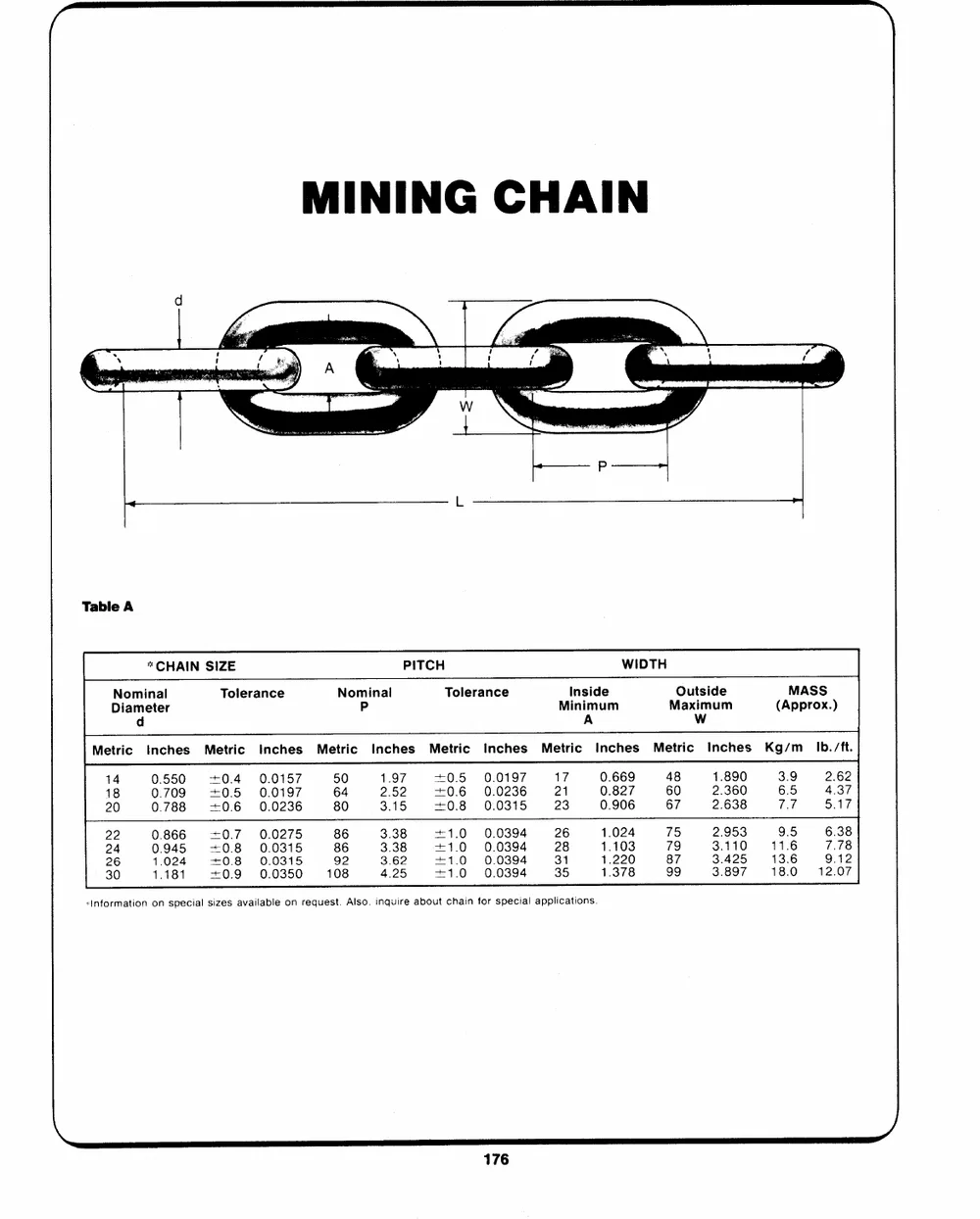
MINING CHAIN
d
` i jo A --_ \ i f ` \ A
i
----_------- P
L >
TablA e
* CHAIN SIZE PITCH WIDTH
Nominal Tolerance Nominal Tolerance MiInnsiimdue m MOauxtismiduem (AMppArSoxS.)
Diameter P
A Ww
Metric Inches Metric Inches Metric Inches Metric Inches Metric Inches Metric Inches Kg/m_ Ib. /ft.
14 00..750590 ++0045 00..00115977 5604 21..5927 ++00..56 00..00129376 2117 00..686297 4680 21..386900 36..59 42..6327
18 0.788 +06 0.0236 80 3.15 +0.8 0.0315 23 0.906 67 2.638 77 5.17
22 0.866 +0.7 0.0275 86 3.38 +1.0 0.0394 26 1.024 75 2.953 9.5 6.38
24 0.945 +08 0.0315 86 3.38 +1.0 0.0394 28 1.103 79 3.110 11.6 7.78
26 1.024 +08 0.0315 92 3.62 ++11..00 00..00339944 3315 11..327280 9879 33..482957 1138.06 129..0172
30 1.181 +0.9 0.0350 108 4.25
�Information on special sizes available on request. Also, inquire about chain for special applications.
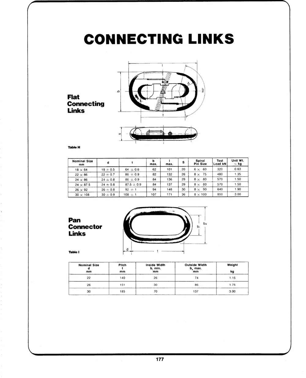
CONNECTING LINKS
Flat Oe iMiaatf
Connectia ng
Sui eeo as ` |
Lise nks
Table H
Nominai Size d t mabx. maIx. s PSipnirSailze LoTaedstkN Un~it kWgt.
mm
18+ 0.5 64 + 0.6 62 101 _20 6x 60 320 0.63
18 x 64 22407 86 + 0.9 82 8x 75 480 1.35
22 x 86 2440.8 86 + 0.9 84 132 26 8x 80 570 1.50
24 x 86 24+0.8 87.5 + 0.9 84 8x 80 570 1.50
24 x 87.5 26+ 0.8 92 +1 94 136 29 8x 90 640 1.90
26 x 92 30 + 0.9 108 +1 107 8 x 100 850 3.00
30 x 108 137 29
146 30
171 36
Pan i d t Outside Width Weight
Connector b, max. kg
Links Pitch tnside Width mm
t b, min. 1.15
Table I mm 74 1.75
mm 3.00
Nominal Size 140 26 86
mm 151 30
185 70 137
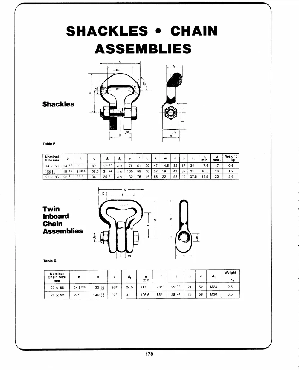
SHACKLES � CHAIN
ASSEMBLIES
Shackles
Table F
SNoimzienmaml b t � q, qd, e f 9 k m A Pp " minr . maux. | W~eigkhgt
14 50 | 14�75] 50! 80 17795 | wm 16 78 | 51 | 29 | 47 | 14.5] 32 117 | 24 7.5 17 0.6
18x84 19�15 | 6475 | 103.5 | 21795 | m2o | 100 | 55 | 40 | 57} 19 | 43. | 37] 31 | 105] 16 1.2
22 x 86 | 22-2 86 ? 134 2571 M24 | 132 | 75 | 461 68| 22 52 | 44 | 37.5) 11.5 20 2.6
Twin
Inboard
Chaii n
Assemblies
Table G
ChNaoimninSailze b c t d, e f . m n Weight
mm +2 i d,
kg
22 x 86 24.5195 132+13 86+! 24.5 117 78t! 25705 24 52 M24 2.5
26 x 92 27+ 146413 g2*! 31 126.5 85+! 28105 26 58 M30 3.5
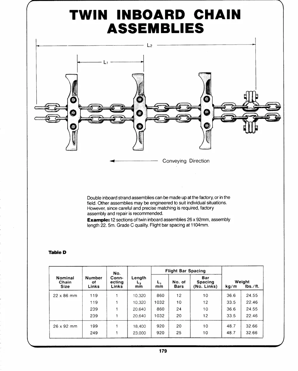
TWIN INBOARD CHAIN
ASSEMBLIES
Le >
A Conveying Direction
Double inboard strand assemblies can be made up at the factory, or in the
field. Other assemblies may be engineered to suit individual situations.
However, since careful and precise matching is required, factory
assembly and repair is recommended.
Example: 12 sections of twin inboard assemblies 26 x 92mm, assembly
length 22. 5m. Grade C quality. Flight bar spacing at 1104mm.
Table D
No Flight Bar Spacing
Conn-
Nominal Number ecting Length L, No. of Bar Weight
Chain of Links L, mm Bars Spacing kg/m Ibs./ft.
Size mm (No. Links)
Links 1
22 x 86 mm 1 10,320 860 12 10 36.6 24.55
119 1 10,320 33.5 22.46
26 x 92mm 119 1 20,640 1032 10 12 36.6 24.55
239 20,640 33.5 22.46
239 1 860 24 10
1 18,400
199 23,000 1032 20 12
920 20 10 48.7 32.66
48.7 32.66
920 25 10
-� W.J. KEATING LIMITED
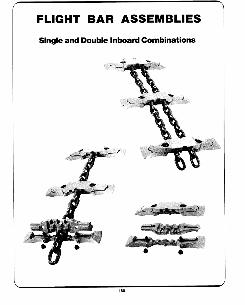
FLIGHT BAR ASSEMBLIES
Single and Double Inboard Combinations
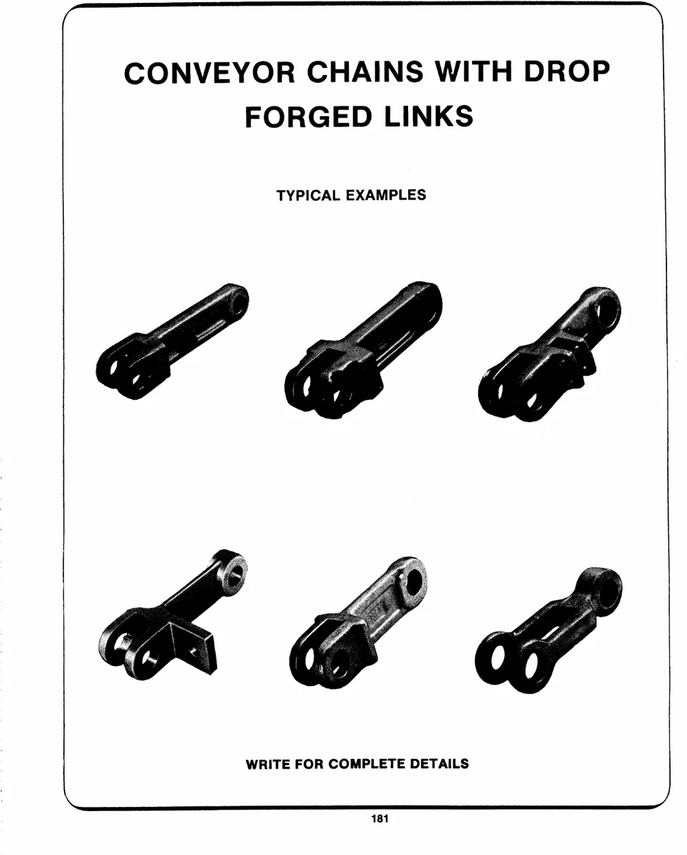
CONVEYOR CHAINS WITH DROP
FORGED LINKS
TYPICAL EXAMPLES
WRITE FOR COMPLETE DETAILS
�TM� W.J. KEATING LIMITED
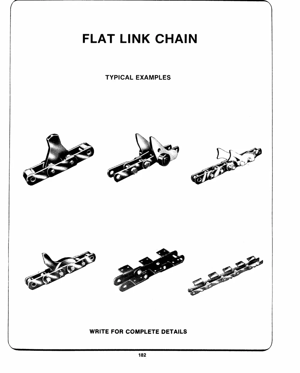
FLAT LINK CHAIN
TYPICAL EXAMPLES
WRITE FOR COMPLETE DETAILS