
Full chapter text (extracted from the original PDF)
Verbatim text extracted from the original chapter PDF (1940–). The original catalog is in English; spec tables may render imperfectly — the PDF remains the authoritative source.
HAND WINCHES
2 Ton & 5 Ton All Steel
Hand Winches
All steel construction with replaceable Optional Features:
bronze bearings � Safety Brake Handle -- load automatically
Fast two-speed gear chan--g4:e1 for slack held when cranking stops
cable take-up only e Marine Models have cable clamp, zinc
One piece handle with adjustable pinion metallized brake drum. rust-resistant paint
� Divided Drum
e Easy free-spooling _ e Reverse Direction Holding Dogs
� Spring loaded holding dog with release
handle ; e 28" Diameter Hand Wheels
e Handle operated adjustable holding brake
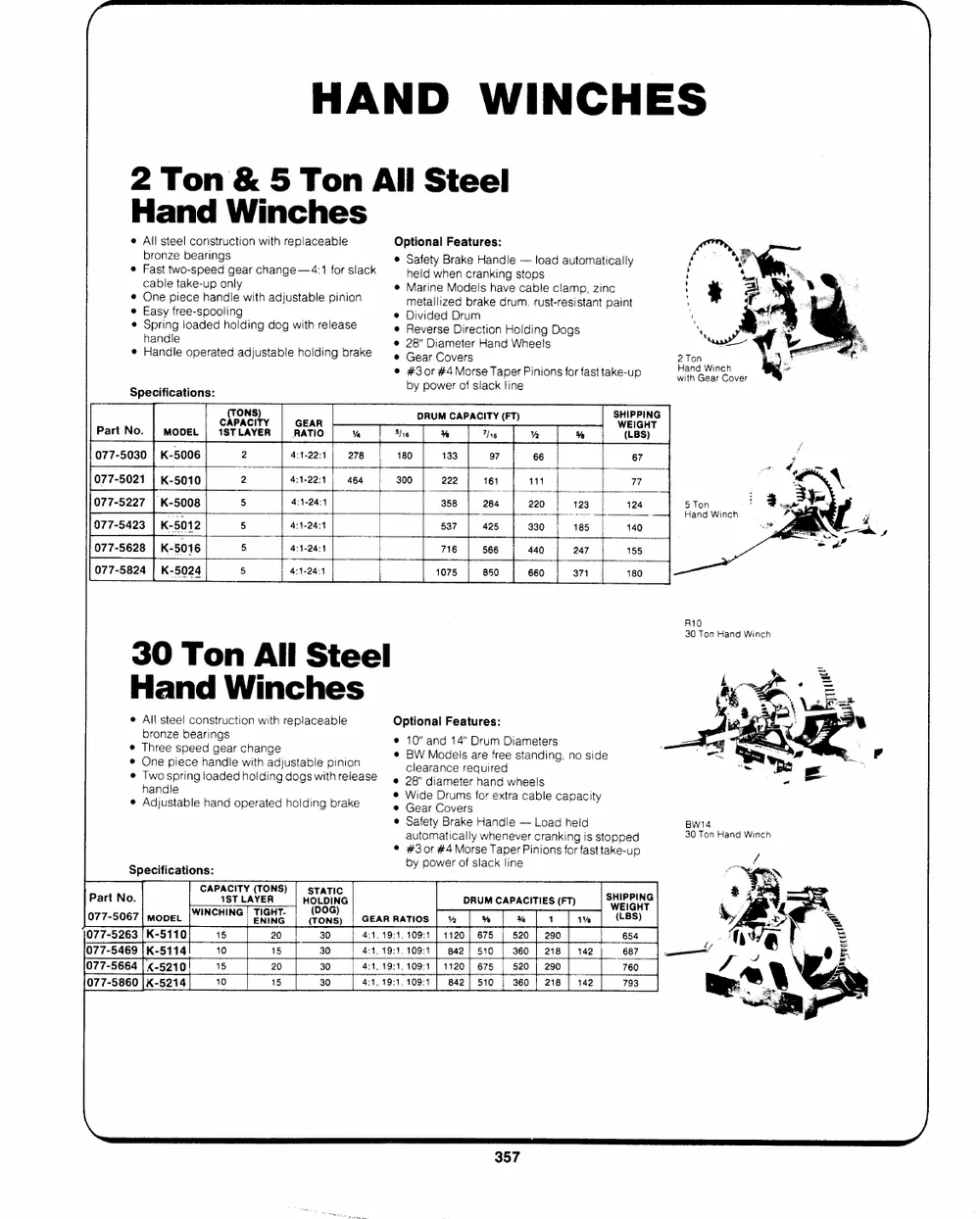
=, Gear Covers 2 Ton
Hand Winch
Specifications: � #301 #4 Morse Taper Pinions for fast take-up with Gear Cover
by� Popower 01f slSalacckk'line 5 Ton
Hand Winch
C(ATPOANCSI)TY GEAR DRUM CAPACITY EN) SWHEIIPPGIHNTG
Part No. | MODEL | 1STLAYER | RATIO % S16 % The Ye 5 (LBS)
077-5030 | K-5006 2 4:1-22:1 | 278 180 133 97 66 67
077-5021 | K-5010 2 4:1-22:1 | 464 300 222 161 111 77
077-5227 |K-5008 5 4:1-24:4 358 | 284 220 123 124
077-5423 | K-5012 5 4:1-24:1 537 | 425 | 330 | 185 140
077-5628 K-5016 5 4:1-24:4 716 566 440 247 155
077-5824 | K-5024 5 4:1-24:4 1075 850 660 371 180
30 Ton All Steel R10
Hand Winches 30 Ton Hand Winch
All steel construction with replaceable Optional Features: BW14
bronze bearings 30 Ton Hand Winch
Three speed gear change 10" and 14" Drum Diameters
One piece handle with adjustable pinion BW Models are free standing, no side
clearance required
Thawnodlsepring loaded holding dogs with release � 28" diameter hand wheels
e Adjnustable hand operated holding brake e� WGiedare CDorvuemrss for extra cable cappaacciitly
Specifsiecsatsions: * Safety Brake Handle --- Load held
automatically whenever cranking is stopped
� #30r #4Morse Taper Pinions for fast take-up
by power of slack line
Part No. CAPA1CSITTLYA(YTEORNS) | HsOtLaDtIiNcG DRUM CAPACITIES (FT) SWEIGn
077-5067| mover|W !NCHING| TIGHT. rDoOnGg)
GEAR RATIOS | % % M% | 1 1% (LBS) Ye .yn �acetuel }
077-5263|K-5110 15 20 30
4:1, 19:1, 109:1 | 1120 | 675 | 520 | 290 654
077-5469 |K-5114 10 15 30
4:1,19:1, 109:1 | 842] 510 | 360 | 218 | 142 687
077-5664| K-5210 15 20 30 4:1, 19:1, 109:1 | 1120] 675 | 520 | 290 760
4:1, 19:1, 109:1 | 842] 510 | 360 | 218 | 142
077-5860 |K-5214 10 15 30 793
WORM GEAR WINCHES
FOR HAND OPERATION
FULLY ENCLOSED GEARS IN OIL BATH
FOR LONG LIFE AND SMOOTH OPERATION
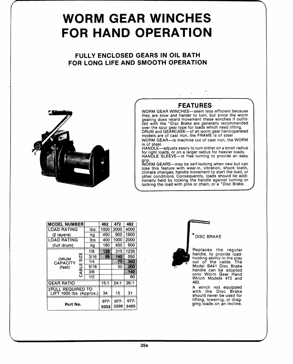
(~ FEATURES |
WORM GEAR WINCHES--seem less efficient because
they are slow and harder to turn, but since the worm
gearing does retard movement these winches if outfit-
ted with the *Disc Brake are generally recommended
over the spur gear type for loads which need lifting.
DRUM and GEARCASE--of all worm gear hand-operated
models are of cast iron, the FRAME is of steel
WORM GEAR--is machine cut of cast iron, the WORM
is of steel.
HANDLE--adjusts easily to turn either on a small radius
for light loads, or on a larger radius for heavier loads.
HANDLE SLEEVE--is free turning to provide an easy
WORM grip. GEARS--may be self-locking when new but can
iose this feature with wear-in, vibration, shock loads,
\_ltocoitloohiknemiaranltlgceyotcnhhdheeialtndligooebansyds,.wlhioCatconhkndispnleigeqnusmtehonoevrtelhcymah,eanidnlnlt,oeatodaorsgsaatsiah*nroDstutitlshdcteurBblnreoiaankadged,.dooi-rr
MODEL NUMBER 462 | 472 | 482
LOAD RATING Ibs | 1000| 2000| 4000
LO(A2 DlayReArsT)ING {kbgs | 445000||1900000||21080000 : * DISC BRAKE
(full drum) kg 180 | 450] 900
Replaces the regular
; handle, to provide load-
W ohuotldionfg atbhileitycaibnlteh.e pTlhaey
a4 | 1/4 hMaonddelle 8c4a4n1beDisacdoBprtaekde
| 5/16 onto Worm Gear Hand
eT 3/8 CADP(fRAeeUCtIM) TY
O |-q2 W48i2n. ch Model: s 472 and
GEAR RATIO 15:14 | 24:1 | 26:4 with the Oise eore
�PULL REQUIRED TO
LIFT 1000 Ibs (Approx.) 34 15 31 should never bi e usedrafkoer
Pert No. 500770-3|| 502770-9|| 077- lifting, lowering, or drag-
5405 ging loads on an incline.
SPUR GEAR WINCHES
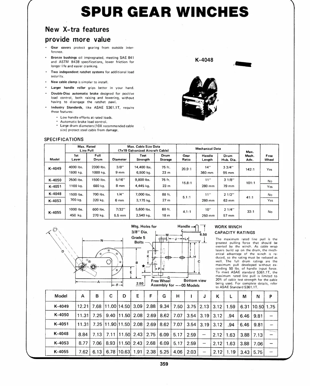
New X-tra features K-4048
provide more value
Gear covers protect gearing from outside inter-
ference.
Bronze bushings oil impregnated, meeting SAE 841
and ASTM B438 specifications, lower friction for
longer life and easier cranking.
Two independent ratchet systems for additional load
security.
New cable clamp is simpler to install.
Larger handle roller grips better in your hand.
Double-Disc automatic brake designed for positive
load control, both raising and lowering, without
having to disengage the ratchet pawl.
tndustry Standards, like ASAE $361.1T, require
these features:
Low handle efforts at rated loads.
Automatic brake load control.
Large drum diameters (10X recommended cable
size) protect steel cable from damage.
SPECIFICATIONS
Max. Rated Max. Cable Size Data Mechanical Data
Line Pull (7x19 Galvanized Aircraft Cable)
Max.
Model Ist Full Diameter Test Drum Gear Handle Drum Mech. Free
Layer Drum Strength Storage Ratio Length Hub. Dia. Adv. Wheel
20.9:1 14231
K-4049 4000 Ibs. 2300 Ibs. 3/8" 14,400 Ibs. 75 ft. 14" 33/4" Yes
1800 kg. 1000 kg. 9mm 6,500 kg. 23 m 15.8: 360 mm 95 mm 101-1
~ , No
K-4050 2500 Ibs. 1500 Ibs. 5/16" 9,800 Ibs. 75 ft. 1" 3 1/8" Yes
680 kg. 8mm 4,445 kg. 23m 280 mm 79 mm at No
K-4051 | 1100kg.
33:1 Yes
K-4048 | 1500 Ibs. 700 Ibs. 1/4" 7,000 Ibs. 88 ft. 541 11" 21/2"
No
K-4053 700 kg. 320 kg. 6mm 3,175 kg. 27m o 280 mm 63 mm
K-4055 1000 Ibs. 600 Ibs. 7/32 5,600 Ibs. 60 ft ait 10 21/4
450 kg. 270 kg. 5.5mm 2,540 kg., 18m 250 mm 57 mm
Mtg. Holes for Handle 4 i | f WORK WINCH
Grade 5 ttt{ 4 3/8" Dia. M 6.50 CTAhePAmCaIxTimYumRArTaIteNdGlSine pull is the
Bolts -- | | { ri - egrxeeartteesdt bpyulltihneg wfionrcceh. Asthat csahbolueldwrabpe
fy `podsmv I layers build up on the drum, the mech-
anical Tashdoevatnhfteuallgraetdinorgfummut= hsetratbwieingnscrhe:daurceies dtrhaees-
B K| yf mY- --42-4 H Cc
x7re 'y wdeulcle.d,
maximum pull developed without ex-
Ef 4 + Pry cTeoedmineget 50ASiAbsE. osftanhdaanrddle$3i6n1pu.t1T,fortche.e
zo] KEM, bane" | --4 G | ~ eget arama maximum rated line pull is limited to
Free Wheel Bottom view 20% of cable test strength for the cable
Mode! A B D E F G H | J K L M N P
K-4049 12.21| 7.68 |11.00/14.50} 3.09| 2.88| 9.34| 7.50| 3.75| 2.13 | 3.12| 1.59 | 6.31 |10.50) 1.75
K-4050 | 11.31] 7.25| 9.40 |11.50] 2.08| 2.69| 8.62) 7.07| 3.54/3.19/3.12| .94 |6.46/9.81} --
K-4051 11.31] 7.25 |11.90}11.50| 2.08| 2.69| 8.62| 7.07 | 3.54] 3.19] 3.12} 94 |6.46/);9.81) --
K-4048 8.84 | 7.13] 7.11 }11.50| 2.43] 2.75} 6.09 | 5.17| 2.59) -- 12.12] 1.63 | 3.8817.13 --
K-4053 8.77| 7.06 | 8.93 }11.50) 2.43| 2.68 | 6.09; 5.17/ 2.59} -- | 2.12] 1.63 | 3.88] 7.06; --
K-4055 7.62 | 6.13 | 6.78 {10.63} 1.91 | 2.38] 5.25| 4.06} 2.03} -- | 2.12] 1.19 | 3.43)5.75| --
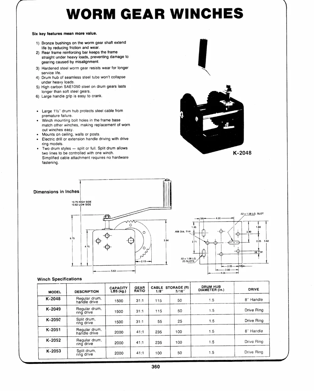
WORM GEAR WINCHES
Six key features mean more value.-- se
1) Bronze bushings on the worm gear shaft extend il a
life by reducing friction and wear. nat
od
2) Rear frame reinforcing bar keeps the frame
straight under heavy loads, preventing damage to 7? P -
gearing caused by misalignment.
al
3) Hardened steel worm gear resists wear for longer
service life.
4) Drum hub of seamless steel tube won't collapse
under heavy loads.
5) High carbon SAE1050 steel on drum gears lasts
longer than soft steel gears.
6) Large handle grip is easy to crank.
� Large 11%" drum hub protects steel cable from
premature failure.
* Winch mounting bolt holes in the frame base
match other winches, making replacement of worn
out winches easy.
Mounts on ceiling, walls or posts.
Electric drill or extension handle driving with drive
ring models.
� Two drum styles -- split or full. Split drum allows
two lines to be controlled with one winch.
Simplified cable attachment requires no hardware
fastening.
Dimensions in Inches
10.75 HIGH SIDE
10.62 LOW SIDE
1.45
406 DIA. TYP.
Mw
Winch Specifications
MODEL DESCRIPTION "BS(ko). RATIO cae sToReAe DIAMETER (in) DRIVE
K-2048 Regularcram, 1500 31-1 115 50 15 8" Handle
K-2049 ring `jnve 1500 34:1 115 50 1.5 Drive Ring
K-205C apo nve 1500 3141 55 25 1.5 Drive Ring
K-2051 Regular drum, 2000 ates 235 100 1.5 8" Handle
K-2052 fieoueum 2000 44:1 235 100 1.5 Drive Ring
K-2053 ney drive 2000 44:1 100 50 1.5 Drive Ring
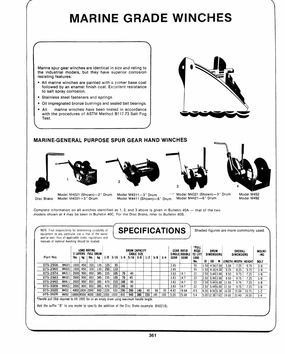
MARINE GRADE WINCHES
( >
Marine spur gear winches are identical in size and rating to
the industrial models, but they have superior corrosion
resisting features:
� All marine winches are painted with a primer base coat
followed by an enamel finish coat. Excellent resistance
to salt spray corrosion.
* Stainless steel fasteners and springs.
� Oil impregnated bronze bushings and sealed ball bearings.
� All marine winches have been tested in accordance
with the procedures of ASTM Method Bi17-73 Salt Fog
Test.
/
MARINE-GENERAL PURPOSE SPUR GEAR HAND WINCHES
Model M4021 (Shown)--2" Drum Model M4311--3" Drum --7 Madel M4321 (Shown)--3" Drum Model M452
Model M4031--3" Drum Model M492
Disc Brake Model M4411 (Shown)--6" Drum Model M4421--6" Drum
Complete information on all winches identified as 1, 2, and 3 above is given in Bulletin 40A -- that of the two
models shown at 4 may be seen in Bulletin 40C. For the Disc Brake, refer to Bulletin 40B.
(wore Final responsibility for determining Suitabilityof [SP ECI FICATI O N S| Shaded figures are more commonly used. \
equipment to any particular use is that of the owner
and/or user; thus all applicable codes, regulations, and
manuals of material handling should be studied.
LOAD RATING DRUM CAPACITY *PULL
GEAR RATIO | REQD
2 LAYERS FULL DRUM ; CABLE SIZE DRUM OVERALL MOUNT-
Part No. SINGLE} DOUBLE| TO LIFT; DIMENSIONS DIMENSIONS ING
Ibs. | kg | Ibs. | kg | 1/8 3/16 | 1/4 ,5/16| 3/8 | 1/2 | 5/8 | 3/4 | GEAR | GEAR | 1000
BOLT
Ibs. 1D | OD | W |LENGTH| WIDTH|HEIGHT) 3/8
3/8
075-2956 M4021; 1000} 450) 300) 135, 125; 55 2.85 55 [1.50] 4.56/2.00) 5.00 | 7.25) 5.75| 3/8
075-2965 M4031; 1000; 450; 300] 135] 250; 110 2.85 378
55 {1.50] 4.56/4.00} 825 825) 5.75] 3/8
3/8
075-2974 M4311) 2000] 900) 850; 385| 235) 105) 70} 45 3.83 [147 22 (2.50) 5.44/3.00} 850 | 9.75) 7.25) 172
3/4
075-2983 M4321} 2000) 900} 850) 385) 235) 105{ 70; 45 3.83 14.7 22 (2.50; 5.44/3.00| 850 | 9.75) 7.25]
075-2992 M4411; 2000] 900; 850) 385) 470; 210}140 , 90 3.83 [14.7 22 (2.50) 5.44/6.00) 11.50 | 9.75] 7.25]
075-3009 M4421/ 2000] 900) 850] 385; 470; 210] 140 | 90 3.83 114.7 22 (2.50) 5.44/6.00| 11.50 | 9.75] 7.25]
075-3020" ~ M452 | 4000/1800 |2000 900/1220| 550| 290 | 200 | 140; 80; 50| 35 | 442 |1954 | 45 14.00) 8.50/6.38! 16.00 | 15.00| 10.75].
075-3029 M492 |10000)4500 4000| 1800|3300|1500| 800 | 540 | 380| 2201145 | 100 | 5.00 |5.00112.38/7.62} 19.00 | 20.40 | 14.00]
[25.00 9.4
*Handle pull (Ibs) required to lift 1000 Ibs on an empty drum using maximum handle length.
Add the suffix 'B'' to any modei to specify the addition of the Disc Brake (example: M4021B).
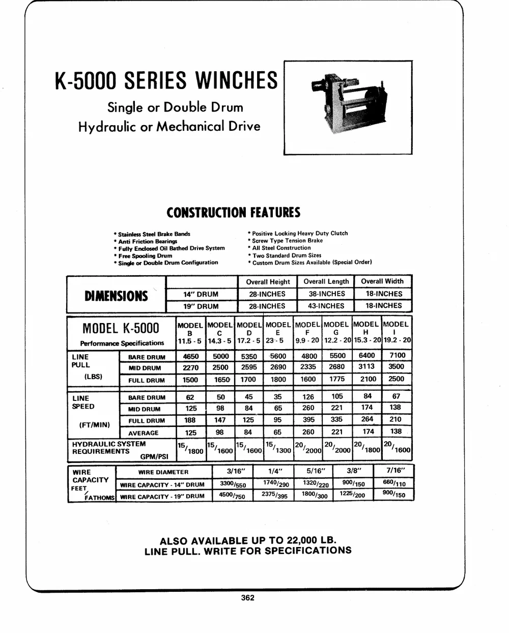
K-5000 SERIES WINCHES
Single or Double Drum
Hydraulic or Mechanical Drive
CONSTRUCTION FEATURES
* Stainless Steel Brake Bands * Positive Locking H eavy Duty Clutch
* Anti Friction Bearings * Screw Type Tension Brake
* Fully Enclosed Oil Bathed Drive System * All Steel Construction
* Free Spooling Drum
* Single or Double Drum Configuration * Two Standard Dru m Sizes
* Custom Drum Sizes Available (Special Order)
.| Overal! Height Overall Length {| Overall Width
28-INCHES
DIMENSIONS � | 14" DRUM 28-INCHES 38-INCHES 18-INCHES
| 19" DRUM 43-INCHES 18-INCHES
M ODEL kK-5000 MODEL |MODEL{ MODEL] MODEL| MODEL|MODEL {MODEL [MODEL
Performance Specifications B Cc D E F G H l
}14.3-5]17.2-5/23-5 [9.9 - 20] 12.2 - 20/15.3 - 20)19.2 - 20
}11.5-5
LINE BARE DRUM 4650 | 5000 | 5350 | 5600 | 4800 | 5500 | 6400 {| 7100
PULL MID DRUM 2270 | 2500 | 2595 | 2690 | 2335 | 2680 | 3113 | 3500
FULLDRUM | 1500 | 1650| 1700 | 1800 | 1600 | 1775 | 2100| 2500
(LBS)
LINE BARE DRUM 62 50 45 35 126 105 84 67
SPEED MID DRUM 125 | 38 84 65 260 | 221 174 | 138
264| 210
(FT/MIN) FULL DRUM 188 147 125 95 395 335 174 138 .
260 221
AVERAGE 125 98 84 65
15,1800] 15,`1600| 5,`1600] 15,`1300] 20,`2000; 20,`2000; 20,`1800} 20,`1600
HRYEDQRUAIURLEIMCENSTYSSTEGMPM/PSI
WIRE WIRE DIAMETER 3/16" 1/4" 5/16" 3/8" 7/16"
1740/5909 1320/5999 | 902/450
weArPACITY WIRE CAPACITY - 14" DRUM 3300/5650 2375/395 | 1800/39 | 1225/2900 660/449
FATHOMS| WIRE CAPACITY -19" DRUM | 4500/75 900/150
ALSO AVAILABLE UP TO 22,000 LB.
LINE PULL. WRITE FOR SPECIFICATIONS
~
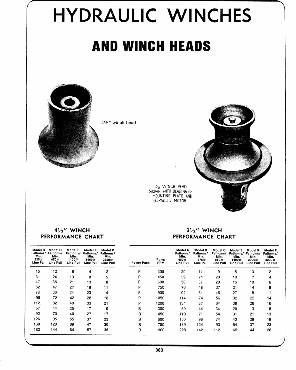
HYDRAULIC WINCHES
AND WINCH HEADS
4�%2" winch head
33 WINCH HEAD
SHOWN WITH BEARINGED
MOUNTING PLATE AND
HYDRAULIC MOTOR
412" WINCH 342" WINCH
PERFORMANCE CHART PERFORMANCE CHART
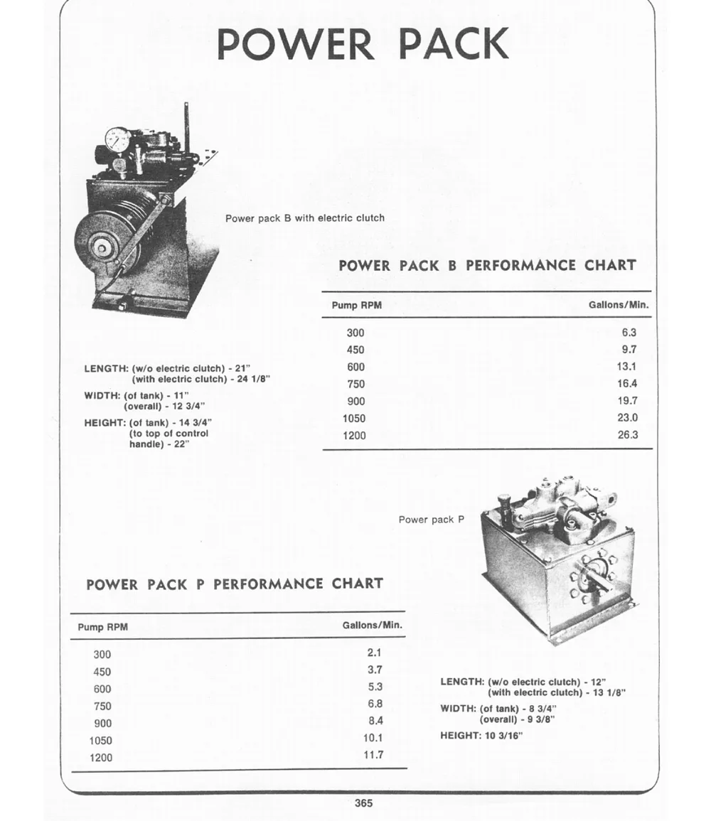
ModelB ModefC ModelE ModelK Model P Power Pack Pump Model A Model B ModelC ModelE Mode!K ModeP!
Fathoms/ Fathoms/ Fathoms/ Fathoms/ Fathoms/ RPM Fathoms/ Fathoms/ Fathoms/ Fathoms/ Fathoms/ Fathoms/
P
Min. Min. Min. Min. Min. Pp 300 Min. Min. Min. Min. Min. Min.
P 450
5254 6504 11004 1550# 25504 P 600 400# 6754 850+ 1400# 2000# 32004
Line Pull Line Pull Line Pull Line Pull Line Pull P 750 Line Pull Line Pull Line Pull Line Pull Line Pull Line Pull
P 900
15 12 6 4 2 P 1050 20 11 9 5 3 2
B 1200
31 24 13 8 5 B 300 39 24 20 10 7 4
47 36 21 13 8 B 58 37 28 16 10 6
62 AT 27 18 11 B 76 48 37 at 14 9
B 750
78 60 34 23 14 900 94 61 46 27 18 11
95 72 42 28 18 114 74 56 32 22 14
112 82 49 33 21 134 87 64 38 26 16
57 44 25 17 10 69 44 34 20 13 8
92 70 40 27 17 110 71 54 31 21 13
126 95 55 37 23 150 98 74 43 29 18
160 120 69 47 30 189 {24 93 54 37 23
182 144 84 57 36 228 142 112 65 44 28
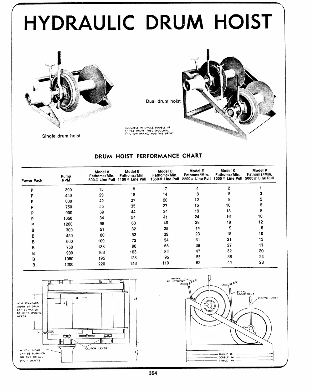
Dual drum hoist
Si. ngle drum hoi`st AVAILABLE IN SINGLE, DOUBLE OR
TRIPLE DRUM. FREE SPOOLING,
FRICTION BRAKE, POSITIVE ORIVE
DRUM HOIST PERFORMANCE CHART
Power Pack PRuPmMp 6F0a0tM#hoodmLeisln/eMAiPnul.l 1F1a0t0Mh#oodmLesil/nMeBiPnu.ll 1F3a5t0Mh4oodmLe3il/nMeCiPnu.ll 2F2a0t0Mh#oodmLesil/nMeEiPnu.ll 3F0a0t0Mh#oodmLesil/nMeKiPnu.ll 5F0a0t0Mh#oodmLesil/nMePiPnu.ll
P 300
P 450 15 8 7 4 2 1
P 600 29 18 14 8 5 3
P 750 42 27 20 12 8 5
P 900 55 35 27 15 10 6
P 1050 69 44 34 19 13 8
P 1200 B4 54 A1 24 16 10
B 300 98 63 46 28 19 12
B 450 51 32 25 14 9 6
B 600 80 52 39 23 15 10
B 750 109 72 54 31 21 13
B 900 138 90 68 39 27 17
B 11025090 166 103 82 47 3328 2204
B 195� 128 95 55 44 28
Tell 220 146 110 62
Il Ht � ADJUSTMENT
| | 6 --- CLUTCH LEVER
14 1S STANDARD -
WIOTH OF DRUM, Bwiw
CAN B� VARIED
TO MEET SPECIFIC NI L
NEEDS
= i a Ji t r = I7
CAN BE SUPPLIED 7 get 99 |
ON ANY OR ALL DeOpUeBLeE 3449.� -- < ------__ 4 _-_+ - )
ve SHAFTS
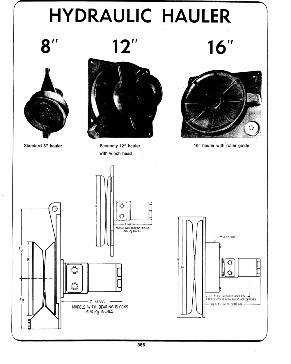
HYDRAULIC H
vi | 12"
Standard 8" hauler Economy 12" hauler 16" haulerwith roller guide
with winch head
T
_
2 C
T MAX iiz ]
MODELS WITH BEARING BLOCKS
7 ADD 25 INCHES Lae Box
i tn
-- \7 | ]
L. |L `
C Lf
P--? | MAX. WITHOUT GEAR BOX
rT MAX. MODELS WITH BEARING BLOCKS ADD 25 INCHES
P-- 82 MAX WITH GEAR BOX ---------=4
MODELS AWDIDTH25BEIANCRHIENSG BLOCKS
LJ
ELECTRIC WINCHES
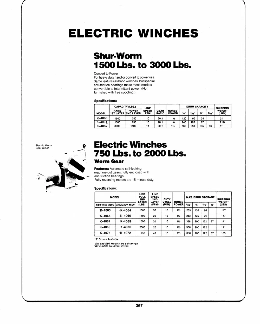
Shur-Worm
1500 Lbs. to 3000 Lbs.
Convert to Power
For heavy duty hand or convert to power use.
Same features as hand winches, but special
anti-friction bearings make these models
convertible to intermittent power. (Not
furnished with free spooling.)
Specifications:
CAPACITY (LBS.) LINE DRUM CAPACITY SHIPPING
HAND POWER | SPEED | GEAR| HORSE- WEIGHT
MODEL [|1STLAYER|2NDLAYER| FPM | RATIO | POWER | %" | "16" | %" | 5/1" | (LBS.)
K-4060 1500 750 10 20:1 Ya 120 | 60] 34 21
K-4061. 1500 750 10 20:1 Ys 240 | 120 | 67 21%
K-4062 3000 1500 11 30:1 1% 560 | 253 | 135 | 96 51
ElEelcecttrriicc WWoorrm g ElecttrriBS c W_ winchnes
|ne 750 Lbs. to 2000 Lbs.
Worm Gear
Features: Automatic self-locking
machine-cut gears, fully enclosed with
anti-friction bearings.
Fully reversing motors are 15-minute duty.
Specifications:
MODEL LINE LINE
P2UNLDL | S2PNEDED| DUTY MAX. DRuUM STORAGE
LAYER | LAYER| CYCLE| HORSE SHIPPING
1/60/115V-230V| 3/60/230V-460V| (LBS) | (FPM) | (MIN) |POWER| 3/16" | 4" | 5/10" | %" WEIGHT
(LBS)
`K-4063 `K-4064 1000 30 15 1�2 } 253 | 135 | 96 117
'K-4065. K-4066 1100 20 15 1% | 253 | 135 | 96 117
K-4067 K-4068. 1500 20 15 1� | 338 | 200 | 122 | 87 111
K-4069 .K-4070 2000 20 10 1�2 | 338 | 200 | 122 111
K-4071� /K-4072 750 43 15 1% 338 | 200 | 122 | 87 105
12" Drums Available
`EW and EBT Mocels are beit driven
2DT models are direct driven
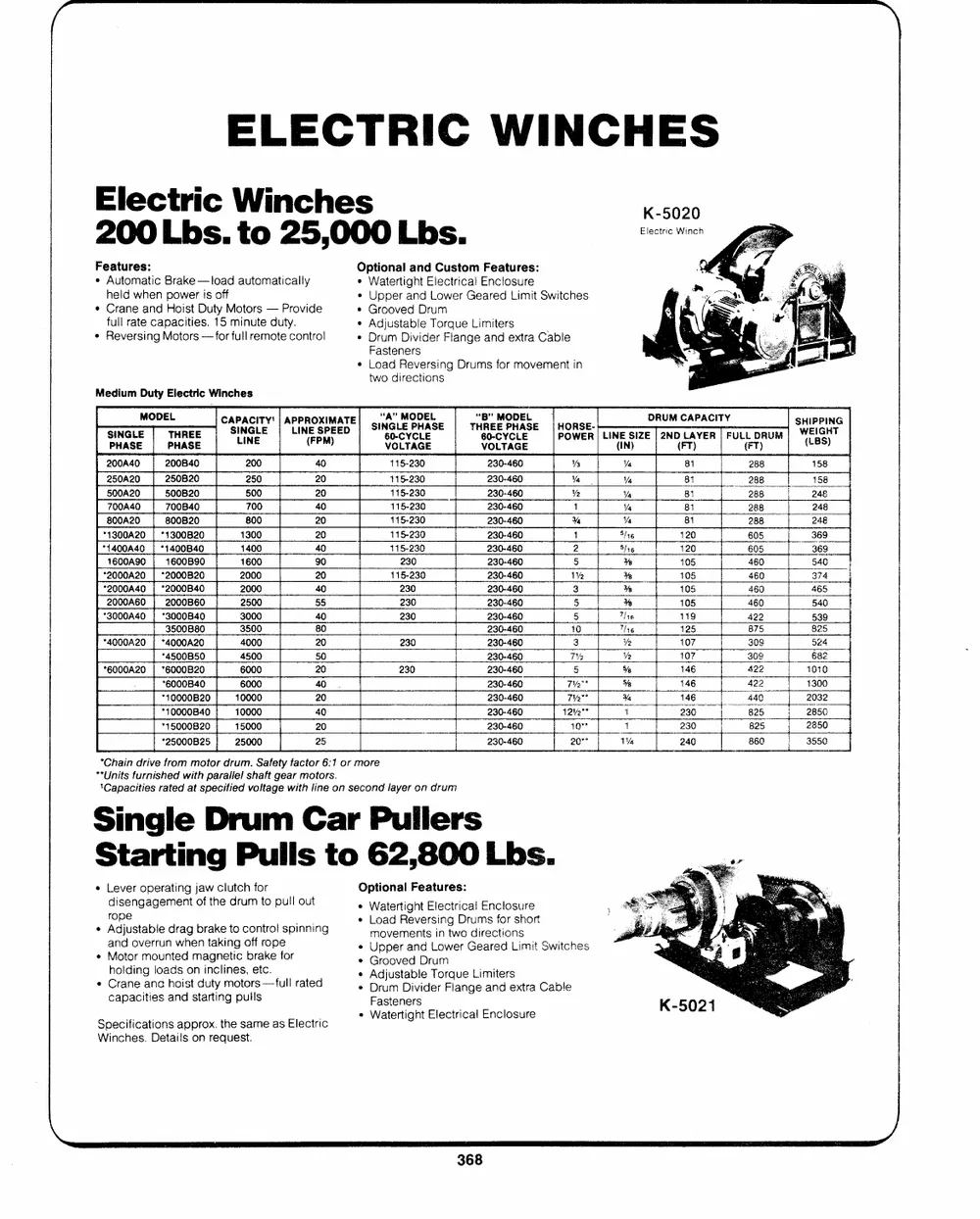
ELECTRIC WINCHES
Electric Winches �5020
200 Lbs. to 25,000 Lbs. sec We
Features: Optional and Custom Features:
� Automatic Brake --load automatically Watertight Electrical Enclosure
held when power is off Upper and Lower Geared Limit Switches
� Crane and Hoist Duty Motors -- Provide
* Grooved Drum
full rate capacities. 15 minute duty. � Adjustable Torque Limiters
e Reversing Motors --for full remote control * Drum Divider Flange and extra Cable
Medium Duty Electric Winches Fasteners
Load Reversing Drums for movement in
two directions
a CATACITY'| APPROXIMATE] SI"NGALME PHASE | TH"RBYEEPHASE |` HORSE- oan crac SHIFPING.
LINE (FPM) 6V0O-LCTYACGLEE 6V0O-LCTYACGLEE POWER| LIN(EINS)IZE |2ND(LFTA)YER| FUL{LFTD)RUM
PHASE PHASE (LBS)
200A40 200B40 200 40 415-230 230-460 Vs Va 81 288 158
250A20 250B20 250 20 115-230 230-460 Va Va 81 288 248
500A20 500B20 500 20 115-230 230-460 Ve "% 81 288 248
700A40 700B40 700 40 115-230 230-460 1 Va 81 288 248
B00A20 800B20 800 20 115-230 230-460 % Ya 81 288 369
*1300A20 | *1300B20 1300 20 115-230 230-460 1 5/16 120 605 369
*1400A40_| *1400B40 1400 40 115-230 230-460 2 5/16 120 605 540
1600A90 | 1600B90 1600 90 230-460 5 % 105 460 374
*2000A20| *2000B20 2000 20 230 230-460 1% � 105 460 465
*2000A40 | "2000B40 2000 40 115-230 230-460 3 % 105 460 540
2000A60 | 2000B60 2500 55 230-460 5 % 105 460 539
*3000A40 | *3000B40 3000 40 230 230-460 5 Thre 119 422 825
3500 80 230 230-460 40 Tlie 125 875 524
3500B80 4000 20 230 230-460 3 Vp 107 30 682
*4000A20 | *4000A20 4500 50 230 230-460 TY Ve 107 309 1010
6000 20 230 230-460 5 56 146 422 4300
*4500B50 6000 40. 230-460 7V2"* 5% 146 422 2032
*6000A20 | *6000B20 10000 20 230-460 Tye % 146 440 285
10000 40 230-460 1242"* 1 230 825 2850
*6000B40 15000 20 230-460 +o" 1 230 825 3550
*40000B20 25000 25
*10000B40 230-460 20"" 1% 240 860
*15000B20
*25000B25
*Chain drive from motor drum. Safety factor 6:1 or more
"*Units furnished with parallel shaft gear motors.
\Capacities rated at specified voltage with line on second layer on drum
Single Drum Car Pullers
Starting Pulls to 62,800 Lbs.
� Lever operating jaw clutch for Optional Features:
disengagement of the drum to pull out * Watertight Electrical Enclosure
� Ardojpuestable drag brake to control spinning * Load Reversing Drums for short
and overrun when taking off rope
movements in two directions
�� Motor mounted magnetic brake for
Upper and Lower Geared Limit Switches
holding loads on inclines, etc.
� Crane ana hoist duty motors --full rated Grooved Drum
capacities and starting pulls � Adjustable Torque Limiters
Drum Divider Flange and extra Cable
Specifications approx. the same as Electric
Winches. Details on request. Fasteners
� Watertight Electrical Enclosure
AIR WINCHES
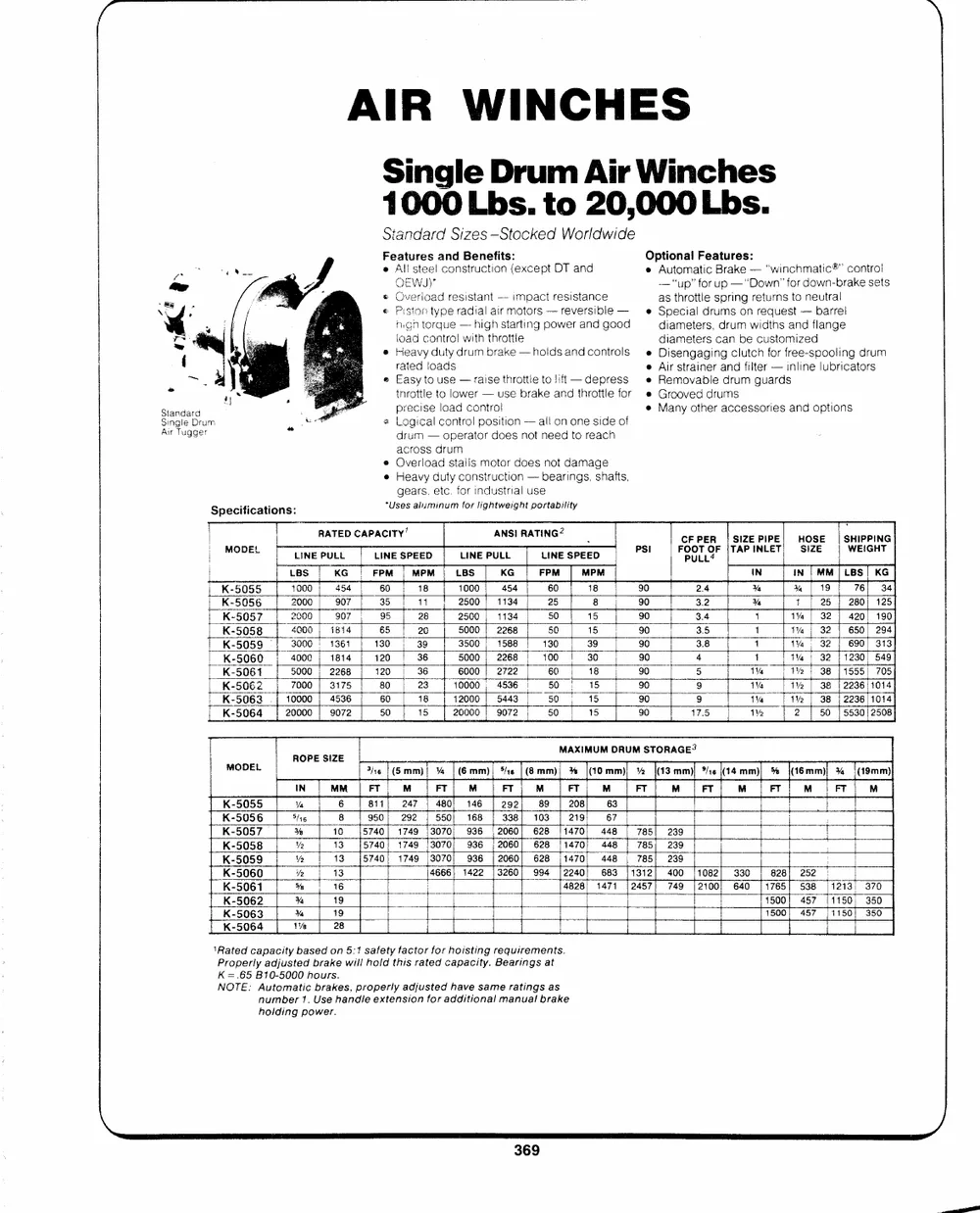
Single Drum Air Winches
1000 Lbs. to 20,000 Lbs.
Standard Sizes --Stocked Worldwide
Features and Benefits:e Optional Features:
All steel construction (except DT and e Automatic Brake -- `winchmatic�" contro!
Standard OEWJ)"
Single Drum Overioad resistant --- impact resistance -- "up" for up -- "Dfo ordw ownn -br" ake sets
Air Tugger as throttle spring returns to neutral
e Piston type radial air motors -- reversible -- e Special drums on request -- barrel
Specifications: nigh torque -- high starting power and good diameters, drum wiaths and flange
ioad control with throttle diameters can be customized
Heavy duty drum brake -- holds and controls Disengaging clutch for free-spooling drum
rated loads
Easy to use -- raise throttie to lift -- depress Air strainer and filter -- inline lubricators
tnrottle to lower -- use brake and throttle for Removable drum guards
precise load control Grooved drums
Logical control position -- all on one side of Many other accessories and options
drum -- operator does not need to reach
across drum
e Overload stalls motor does not damage
Heavy duty construction -- bearings, shafts,
gears. etc. for industrial use
*Uses aluminum for lightweight portability
MODEL RATED CAPACITY' ANSI RATING? CFPER |SIZEPIPE| HOSE | SHIPPING
LINE PULL LINE SPEED LINE PULL LINE SPEED PSI oor oF TAPINLET) SIZE WEIGHT
LBS KG FPM | MPM | LBS KG FPM MPM IN In | MM /LBS| KG
K-5055 1000 454 60 18 1000 454 60 18 90 2.4 Ya �% | 19 76| 34
K-5056 2000 907 35 "4 2500 | 1134 25 8 90 3.2 Ya 1 | 25 | 280] 125
K-5057 2900 907 95 28 2500 | 1134 50 15 90 3.4 j 1% | 32 | 420/ 190
K-5058 4000 | 1814 65 20 5000 | 2268 50 15 90 3.5 1 tv | 32 | 650| 294
K-5059 | 3000 1361 130 39 3500 | 1588 130 39 90 3.8 1 1a | 32 | 690] 313
K-5060 4000 | 1814 120 36 5000 | 2268 100 30 90 4 1 1% | 32 11230! 549
K-5061 5000 | 2268 120 36 6000 | 2722 60 | 18 90 5 1%. 1�2 | 38 11555) 705
K-5062 7000 | 3175 80 23 10000 , 4536 50 15 90 9 1% 1% | 38 | 2236/1014
K-5063 .| 10000 | 4536 60 18 42000 | 5443 50 15 90 9 1V4 1�2 | 38 | 2236/1014
K-5064 20000 | 9072 50 15 26000 | 9072 50 15 90 17.5 1% 2 | 56 | 5530/2508
MODEL ROPE SIZE MAXIMUM DRUM STORAGE?
K-5055 Jig (5mm)! % | (6Emm)| 46 | (8mm), % (10mm) % (43mm) Ze (14mm) % (16mm) 3% |(19mm)
K-5056 IN MM | FT M FT| M FT M FT M FT M FT M FT M FT M
K-5057 --
K-5058 Va 6 8111 247 | 480} 146 | 292 89 | 208 63
K-5059
5/46 8 950; 292 | 550; 168 | 338] 103 | 219| 67
K-5060
% 10 15740] 1749 |3070/ 936 [2060] 628 1/1470) 448 [| 785] 239 |
K-5061
K-5062 Ve 13 [57401 1749 |3070) 936 | 2060] 628 [1470] 448 | 785| 239 '
K-5063
K-5064 Vp 13 15740} 1749 [3070] 936 | 2060| 628 [1470| 448 | 785] 239
ip 13 4666; 1422 |3260|} 994 |2240! 683 [1312] 400 /1082) 330 | 828) 252
5 16 4828] 1471 |2457| 749 {2100 640 |1765| 538 [1213) 370
% 19 1500! 457 11150) 350
1500/ 457 [11501 350
M% 19
1% 28
`Rated capacity based on 5:1 safety factor for hoisting requirements.
Properly adjusted brake wili hold this rated capacity. Bearings at
K =.65 B10-5000 hours.
NOTE: Automatic brakes, properly adjusted have same ratings as
number 1. Use handle extension for additional manual brake
holding power.
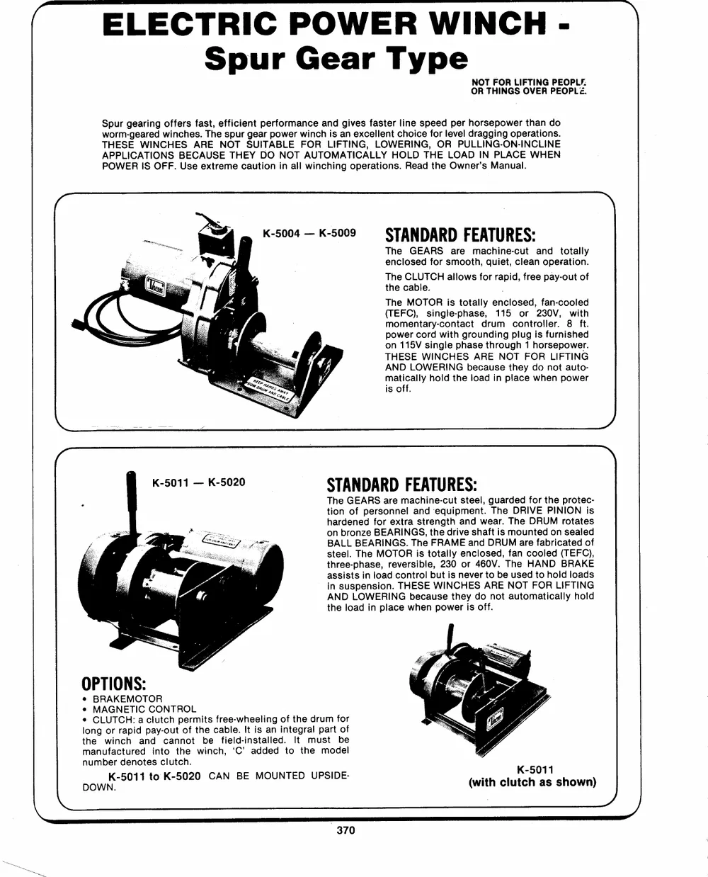
ELECTRIC POWER WINCH-
Spur Gear Type
NOT FOR LIFTING PEOPLF.
OR THINGS OVER PEOPL�.
Spur gearing offers fast, efficient performance and gives faster line speed per horsepower than do
worm-geared winches. The spur gear power winch is an excellent choice for level dragging operations.
THESE WINCHES ARE NOT SUITABLE FOR LIFTING, LOWERING, OR PULLING-ON-INCLINE
APPLICATIONS BECAUSE THEY DO NOT AUTOMATICALLY HOLD THE LOAD IN PLACE WHEN
POWER IS OFF. Use extreme caution in all winching operations. Read the Owner's Manual.
K-5004 -- K-5009 = STANDARD FEATURES:
The GEARS are machine-cut and totally
enclosed for smooth, quiet, clean operation.
The CLUTCH allows for rapid, free pay-out of
the cable.
The MOTOR is totally enclosed, fan-cooled
(TEFC), single-phase, 115 or 230V, with
momentary-contact drum controller. 8 ft.
power cord with grounding plug is furnished
on 115V single phase through 1 horsepower.
THESE WINCHES ARE NOT FOR LIFTING
AND LOWERING because they do not auto-
matically hold the load in place when power
is off.
K-5011 -- K-5020 ~
STANDARD FEATURES:
The GEARS are machine-cut steel, guarded for the protec-
tion of personnel and equipment. The DRIVE PINION is
hardened for extra strength and wear. The DRUM rotates
on bronze BEARINGS, the drive shaft is mounted on sealed
BALL BEARINGS. The FRAME and DRUM are fabricated of
steel. The MOTOR is totally enclosed, fan cooled (TEFC),
three-phase, reversible, 230 or 460V. The HAND BRAKE
assists in load control but is never to be used to hold loads
in suspension. THESE WINCHES ARE NOT FOR LIFTING
AND LOWERING because they do not automatically hold
the load in place when power is off.
OPTIONS: (with clutKc-h50a1s1 shown)
� BRAKEMOTOR
� MAGNETIC CONTROL
� CLUTCH: a clutch permits free-wheeling of the drum for
long or rapid pay-out of the cable. It is an integral part of
the winch and cannot be field-installed. it must be
manufactured into the winch, `C' added to the model
number denotes clutch.
DOWN.K-5011 to K-5020 CAN BE MOUNTED UPSIDE-
POWER WINCH SERIES (\ SPECIFI|CATIONS )> >
, NOT FOR LIFTING PEOPLE
OR THINGS OVER PEOPLE
SERIES K-5004 | K-5005 | K-5007 | K-5009 | K-5011 | K-5013 | K-5014 | K-5015 | K-5017 | K-5018 | K-5019 | K-5020
HORSEPOWER 1/2 3/4 1 1-1/2 2 3 5. 2 3 5 71/2 10
2ND| FULL | 2ND | FULL | 2ND | FULL | 2ND | FULL| 2ND| FULL| 2ND| FULL | 2ND| FULL| 2ND | FULL | 2NO | FULL | 2ND| FULL | 2ND| FULL |: 2ND| FULL
LAYER|DRUM| LAYER| DRUM| LAYER| DRUM] LAYER| DRUM| LAYER| DRUM| LAYER|DRUM| LAYER] DRUM| LAYER| DRUM| LAYER| DRUM| LAYER| DRUM| LAYER| DRUM| LAYER|DRUM
LOAD ibs 600 | 250 | 900 | 370| 1200] 500| 1800| 750| 1400] 800| 2000| 1200| 3500| 2000 | 1400| 700 | 2000 | 1000| 3500| 1750| 5000| 2500| 7000| 3500
RATING kg| 270| 110| 400| 160 | 540] 225| 810| 340 | 635} 360] 900| 540{ 1580] 900] 635] 310| 900] 450] 1580] 790| 2260| 1100| 3100| 1580
DRUM 1/8} 65 | 600 | 65 | 600| 65| 600} 65| 600 | 100] 1235] 100/1235| 100] 1235| 170[3500| 170] 3500 170| 3500] 170] 3500] 170} 3500
CAPACITY Wig, 3/16{ 45| 270 | 45| 270 | 45 270 | 45| 270 | 70| 550| 70] 550{ 70] 550| 110/ 1580] 110] 1580] 110[1580| 120] 1580 110| 1580
(FEET) wu ial 35 | 140 | 35 | 140 | 95{ 140 | 35] 140 | 55] 300] 55) 300) 55| 300} 90/ a50| 90] 850} 90] 850| 90| 850] 90] aso
sHadeD == HD 5716] 30] 90] 30} 90] 30]. 90) 30] 90] 45] 200| 45] 200) 45| 200| 70) 570| 70| 570] 70| 570| 70| 570) 70| S70
Figures &~ 37/8] 25) 70 | 25] 70} 25| 70] 25] 70) 35) 140] 35} 140] 35] 140] 60] 410) 60) 410] 60) 410} 60] 410| 60] 410
ARE MORE 12 30 | 80] 30] 80| 30] 80] So} 240} 50] 240] 50| 240] 50] 240] 50] 240
COMMONLY USED 5/8 35| 150] 35] 150} 35] 150] 35] 150] 35] 150
LINE SPE-E FPDM 21} 40] 21| 4o| 21] 40] 21] 40| 40} 65{ 40] 65] 40] 65} 35) 75] 35] 75] 35{ 75{ 35) 75| 35] 75
65 203 270
WEI-GAPPHROTX. Ibs. 60 _8 95 225 240 290 305 341 382
K-5004 -- K-5009 ALL DRUM CAPACITIES
shown in the table above are based upon
uniform cable winding. Considerable over-lap-
ping often occurs in actual practice, especially
with small cables. This will reduce the
capacities approximately 25%-30%. The
amount of tension applied when spooling the
cable will also affect the amount of cable that
can be held on the drum.
SAFETY TIP
Depending upon the nature of your work, the
load. should not exceed 1/3 to 1/5 the breaking
strength of new cable. For safety, we recom-
mend the load NEVER exceed 1/3 the breaking
strength. Consult a cable supplier for size and
type of cable for your application. Cable is not
supplied with the winch. ,
BREAKING STRENGTH OF |
NEW 7 X 19 GALVANIZED
AIRCRAFT CABLE
Steel Pounds
Cable Diameter
3/4" 49,600
5/8" 35,000
K-5011 -- K-5020 1/2" 22,800
(with clutch) 3/8" 14,400
9/16" 9,800
1/4" 7,000
3/16" 4,200
1/8" 2,000
ao Final responsibility for determining suitability
KHOLETAS Sj} of equipment to any particular use is that of the
owner and/or user; thus, all applicable codes,
mn
should be studied. regulations, and manuals of material handling
dk
DIMENSIONS (Inches)
SERIES | 10 OD WH A B c}]od EF F{G H JS] kK t mM{iEN P QfieRe s tlu vazafy. x
K-5004/ 2.50 6.00 6.00] 1.53 4.06 6.78) 9.78 10.28 11.93}13.58 2288 80] 62 1.88 5.50/10.38 11.00 11.10] 05 4.00 .25 115.00 6.88 11.00] 42 4 HOLES
K-5011] 4.00 8.50 6.50] 1.00 4.06 10.69} 20.38 21.38 7.81{22.00 62 5.88|12.88 13.50 16.62 24.38 1.50 38 536 HOLES
K-5011] 4.00 8.50 6.50] 1.00 4.06 10.69}20.38 21.38 7.81]22.00 62 9.00}16.00 16.62 19.75 24.38 1.50 38 53 6 HOLES
K-5015} 5.00 12.38 7.34] 2.25 6.62 16.00}29.75 32.00 9.50] 23.12 75 6.88/14.75 15.50 24.00] 5.75 32.38 38 18 6 HOLES
K-5015] 5.00 12.38 7.34] 2.25. 6.62 16.00{29.75 32.00 9.50} 23.12 75 10.12]18.00 18.75 27.25| 5.75 32.38 38 78 6 HOLES
al! figures (but "'X"') designate inches.
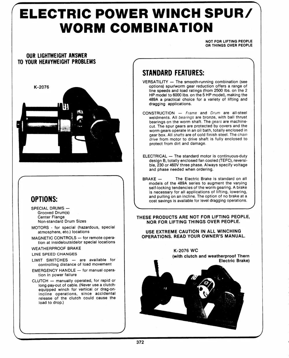
(ELECTRIC POWER WINCH SPUR/
WORM COMBINATION
NOT FOR LIFTING PEOPLE
OR THINGS OVER PEOPLE
OUR LIGHTWEIGHT ANSWER (- >
TO YOUR HEAVYWEIGHT PROBLEMS
STANDARD FEATURES:
VERSATILITY -- The smooth-running combination (see
options) spur/worm gear reduction offers a range of
line speeds and load ratings (from 2500 Ibs. on the 2
HP model to 6000 Ibs. on the 5 HP model), making the
489A a practical choice for a variety of lifting and
dragging applications.
CONSTRUCTION -- Frame and Drum are all-steel
weldments. All bearings are bronze, with ball thrust
bearings on the worm shaft. The gears are machine-
cut. The spur gears are protected by covers and the
worm gears operate in an oil bath, totally enclosed in
gear box. Ail shafts are of cold finish steel. The chain
drive from motor to drive shaft is fully enclosed to
protect from dirt and damage.
ELECTRICAL -- The standard motor is continuous-duty
design B, totally enclosed fan cooled (TEFC), reversi-
ble, 230 or 460V three phase. Always specify voltage
and phase needed when ordering.
BRAKE -- The Electric Brake is standard on all
models of the 489A series to augment the varying
self-locking tendencies of the worm gearing. A brake
is necessary for all applications of lifting, lowering,
caonsdt psualvliinnggsoins aanvaiinlcalbilnee.foTrhleevoelptdiroanggoifnngoopberraakteioantsa.
OPTIONS: q
SPECIAL DRUMS -- THESE PRODUCTS ARE NOT FOR LIFTING PEOPLE,
Grooved Drum(s) NOR FOR LIFTING THINGS OVER PEOPLE.
Center Flange USE EXTREME CAUTION IN ALL WINCHING
Non-standard Drum Sizes
OPERATIONS. READ YOUR OWNER'S MANUAL.
MOTORS - for special (hazardous, special
atmosphere, etc.) locations K-2076 WC
(with clutch and weatherproof Thern
MAGNETIC CONTROLS -- for remote opera-
tion at inside/outside/or special locations Electric Brake)
WEATHERPROOF BRAKE
LINE SPEED CHANGES
LIMIT SWITCHES --- are available for
controlling distance of load movement
EMERGENCY HANDLE --for manual opera-
tion in power failure
CLUTCH -- manually operated, for rapid or
long pay-out of cable. (Never use a clutch-
equipped winch for vertical or drag-on-
incline operations, since accidental
release of the clutch could cause the
load to drop.)
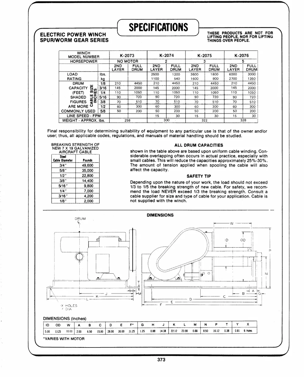
(ELECTRIC POWER WINCH LL SPECIFICATIONS || THESE PRODUCTTSS .AARREE. NNOOTTFFOORR--\
SPUR/WORM GEAR SERIES THINGS OVER PEOPLE.
MODEL NUMBER K-2073 K-2074 K-2075 K-2076
NO MOTOR 2 3 5
HORSEPOWER
2ND FULL 2ND FULL 2ND FULL 2ND FULL
LAYER DRUM LAYER DRUM LAYER DRUM LAYER DRUM
RLAOTAIDNG Ikbgs. 210 21510000 1524000 31660000 1880000 62070000 31035000
DRUM | 1/8 4450 210 4450 210 4450 210 4450
CA(PFAEECTI)TY ONwl| 31//146 114150 12005000 114150 21000500 114150 21000500 111450 21000500
90 720 50 720 90 720 90 720
SHADED 46/56 70 510 70 510 70 510 70 510
FIGURES %2! 3/8 300 60 300 60 300 60 300
ARE MORE? | 14/2 60
COMMONLY USED| 5/8 50 200 50 200 50 200 50 200
LINE SPEED - FPM 15 : 30 15 30 15 30
WEIGHT - APPROX. Ibs. 258 300_--C; 322 328
Final responsibility for determining suitability of equipment to any particular use is that of the owner and/or
user; thus, all applicable codes, regulations, and manuals of material handling should be studied.
BREAKING STRENGTH OF . ALL DRUM CAPACITIES .
NEW 7 X 19 GALVANIZED .
shown in the table above are based upon uniform cable winding. Con-
AIRCRAFT CABLE
Steel siderable. overlapping often occurs in actual practice, especially with
Cable Diameter Pounds small cables. This will reduce the capacities approximately 25%-30%.
3/4" 49,600 The amount of tension applied when spooling the cable will also
5/8" 35,000 affect the capacity.
1/2" 22,800 SAFETY TIP
3/8" 14,400 Depending upon the nature of your work, the load should not exceed
5/16" 9,800 1/3 to 1/5 the breaking strength of new cable. For safety, we recom-
1/4" 7,000 mend the load NEVER exceed 1/3 the breaking strength. Consult a
3/16" 4,200 cable supplier for size and type of cable for your application. Cable is
1/8" 2,000 not supplied with the winch.
DIMENSIONS
DIMENSIONS (Inches)
iD OD WIA B cl|oD --E Ft | G@ 4H J K LM jN POT Y xX
5.00 13.25 10.00] 200 6.50 15.00 | 28.00 30.00 31.25 | 125 088 14.38 | 2212 23.00 0.88 | 850 16.12 0.38 | 0.81 6 Holes
a VARIES WITH MOTOR CS)
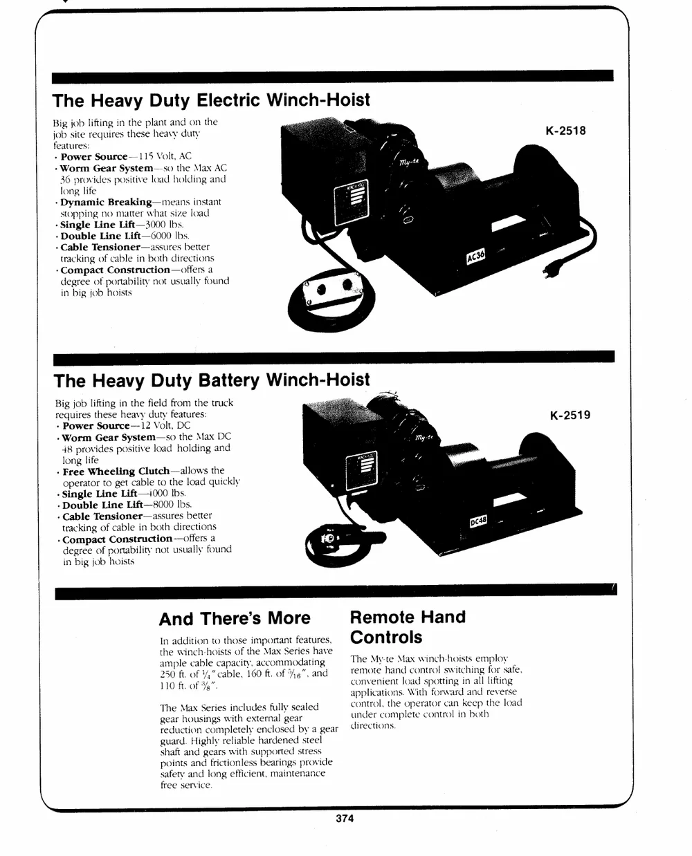
The Heavy Duty Electric Winch-Hoist
Big job lifting in the plant and on the
job site requires these heavy duty
features:
- Power Source--115 Volt, AC
- Worm Gear System--so the Max AC
36 provides positive load holding and
long life
- Dynamic Breaking--means instant
stopping no matter what size load
- Single Line Lift--3000 lbs.
- Double Line Lift--06000 Ibs.
- Cable Tensioner--assures better
tracking of cable in both directions
-Compact Construction--offers a
degree of portability not usually found
in big job hoists
Big job lifting in the field from the truck
requires these heavy duty features:
- Power Source--12 Volt, DC
- Worm Gear System--so the Max DC
48 provides positive load holding and
long life
- Free Wheeling Clutch--allows the
operator to get cable to the load quickly
- Single Line Lift--+000 Ibs.
- Double Line Lift--8000 Ibs.
- Cable Tensioner--assures better
tracking of cable in both directions
- Compact Construction--offers a
degree of portability not usually found
in big job hoists
And There's More Remote Hand
In addition to those important features, Controls
at2h5me0plwfeti.noccfahb-�lh,eo"icscaatpbsalceoi,ftyt1,h6ea0cMfcta.oxomfmSo4erd4i"ae,tsiahnnagdve
TrhemeoMtye-theanMdaxcownitrnoclh-shwoiitscthsinegmpfloroysafe.
110 ft. of 34".
The Max Series includes fully sealed convenient Joad spotting in all lifting
gear housings with external gear
applications. With forward and reverse
control, the operator can keep the load
under complete control in both
reduction completely enclosed by a gear directions.
guard. Highly reliable hardened steel
shaft and gears with supported stress
points and frictionless bearings provide
safety and long efficient, maintenance
w
free service.
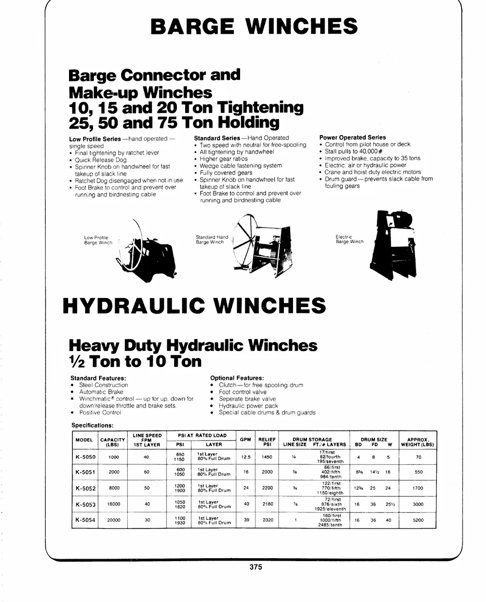
BARGE WINCHES
Barge Connector and
Make-up Winches
10, 15 and 20 Ton Tightening
25, 50 and 75 Ton Holding
Low Profile Series --hand operated -- Standard Series --Hand Operated Power Operated Series
single speed * Two speed with neutral for free-spooling * Control from pilot house or deck
� All tightening by handwheel * Stall pulls to 40,0004
Final tightening by ratchet lever � Higher gear ratios
� Wedge cable fastening system � Improved brake, capacity to 35 tons
Quick Release Dog
Spinner Knob on handwheel for fast � Fully covered gears e Electric, air or hydraulic power
takeup of slack line � Spinner Knob on handwheel for fast � Crane and hoist duty electric motors
Ratchet Dog disengaged when not in use � Drum guard--prevents slack cable from
Foot Brake to control and prevent over takeup of slack line
running and birdnesting cable � Foot Brake to control and prevent over fouling gears
running and birdnesting cable
Low Profile Standard Hand Electric
Barge Winch Barge Winch
Barge Winch
Heavy Duty Hydraulic Winches
Standard Features: Optional Features:
� Steel Construction e Clutch--for free spooling drum
e Automatic Brake e Foot control valve
e Winchmatic� control -- up for up, down for e Seperate brake valve
downrelease throttle and brake sets. e Hydraulic power pack
e Positive Control e Special cable drums & drum guards
Specifications: LINE SPEED PSI AT RATED LOAD GPM | RPELSI!EF LINEDSRIUZME STFOTR/A#GLEAYERS | BDDRUMFDSIZE W_ #|WAEPIPGHRTO(XL.BS)
MODEL | CA(PLABCSI) TY
1ST LPAYER Ps! LAYER 70
1615500 18s0t %LaFyuellr Drum 12.5 17/first 4
K-5050 1000 40 1450 Va 185 soon hn 8 5
K-5051 2000 60 1600500 8ts0t%LaFyulelr Drum 16 2000 Y% 40626//ffiifrtsht 6% 14% 16 550
984/tenth
K-5052 8000 50 11290000 t8s0t%LaFyulelr Drum 24 2200 % 717202//ffiifrtsht 12% 25 24 1700
1150/eighth
K-5053 46000 40 11085500 B1sot%LaPuylelr Drum 40 2180 % 87762//stiirxstth 16 36 25% 3000
1925/eleventh
K-- 5054 20000 30 14913000 81s0t%LaFuylelr Drum 39 2320 1 1010600)/ffii: rfstth 16 36 40 5200
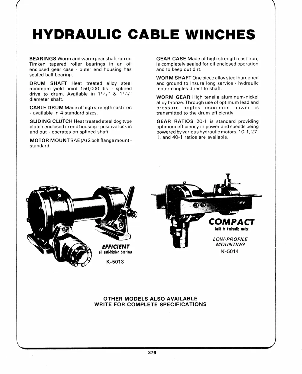
HYDRAULIC CABLE WINCHES
BEARINGS Worm and worm gear shaft run on GEAR CASE Made of high strength cast iron,
Timken tapered roller bearings in an oil is completely sealed for oil enclosed operation
enclosed gear case - outer end housing has and to keep out dirt.
sealelded baball l beariinngg. WORM SHAFT One pi; ece alloy steel hardened
DRUM SHAFT Heat treated alloy steel and ground to insure long service - hydraulic
minimum yield point 150,000 Ibs. - splined motor couples direct to shaft.
ddriiveamettero sdhaft . Avvaainlaambeleiinn ` � 11& 71, 1/7" ," WORM GEAR High tensi,le alumi;num-nic; kel
CABLE DRUM Madeof high strength cast iron alloy bronze. Through use of optimum lead and
- available in 4 standard sizes. pressure angles maximum power is
transmitted to the drum efficiently.
SLIDING CLUTCHHeattreatedsteel dog type
clutch enclosed in end housing - positive lock in GEAR RATIOS 20-1 is standard providing
and out - operates on splined shaft. optimum efficiency in power and speeds being
powered by various hydraulic motors. 10-1, 27-
MOTOR MOUN(AT )2bSoltAflaE nge mount-
1, and 4040--1 ratios are avaiillaabbllee.
standard.
ieCEO COMPACT
built in hydraulic motor
EFFICIENT
J LMOWO-UPNRTOIFNIGLE
all anti-friction bearings K-5014
K-5013
OTHER MODELS ALSO AVAILABLE
WRITE FOR COMPLETE SPECIFICATIONS
~\
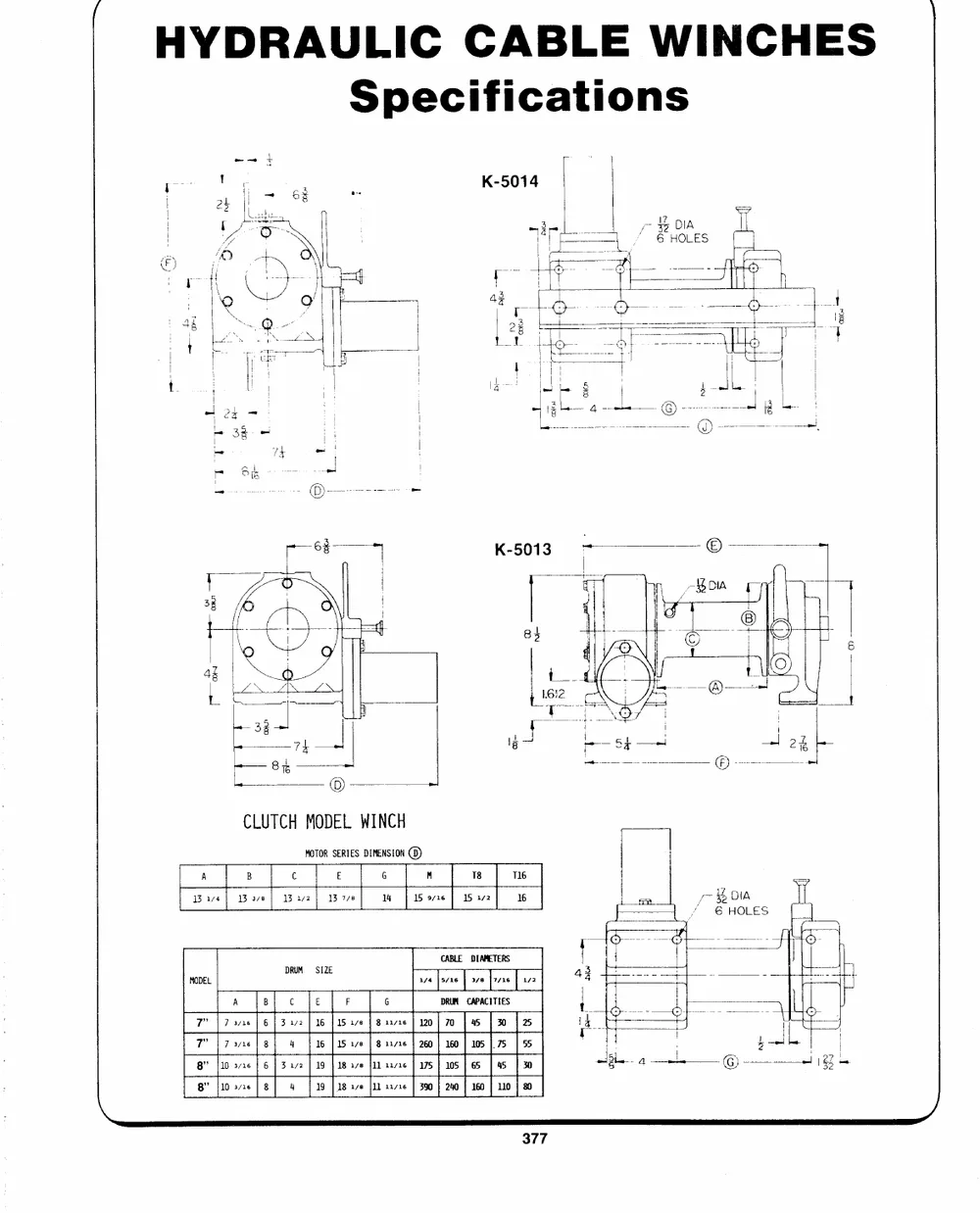
HYDRAULIC CABLE WINCHES
Specifications
yeDIA
6 HOLES
CLUTCH MODEL WINCH
MOTOR SERIES DIMENSION 6)
A B C E 6 M 18 T16
1314 Boa 13 172 13 778 14 15 9/16 15 172 16 y~ OIA
/ 6 HOLES
MODEL DRUM = SIZE CABLE DIAMETERS
asa |eva6 | 378 |rae | Ls2
A B c E F G DRUM CAPACITIES
7" | 7 3/16 | 6 | 3272 | 16 115276 | 8 rx716 | 120} 70 | 45 | 30 | 25
7" | 737x618) 4 | 16 | 15 178 | 8 12726 | 260 | 160 | 105 |. 75 | 55
8" {10 3716 | 6 | 3.172 | 19 | 18278 411 aayre | 175 | 105 | 65 | 45 | BO
8" [10 3/16 | 8 4 19 | 18 1/6 |1} 11716 | 390 | 240 | 160 | 110 | 80
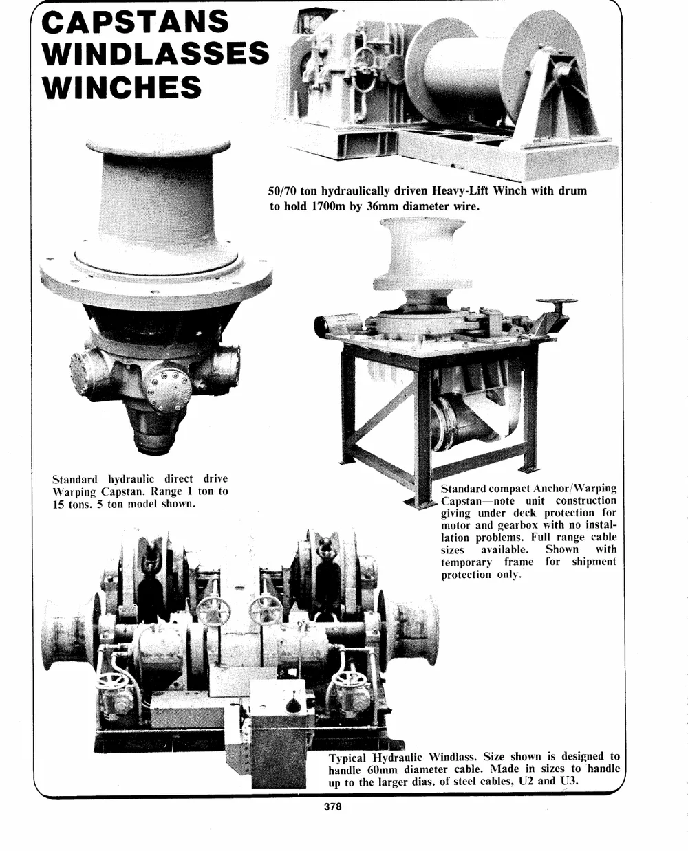
CAPSTANS
WINDLASSES|
WINCHES
50/70 ton hydraulically driven Heavy-Lift Winch with drum
to hold 1700m by 36mm diameter wire.
Standard hydraulic direct drive Standard compact Anchor/Warping
Warping Capstan. Range I ton to Capstan--note unit construction
15 tons. 5 ton model shown. giving under deck protection for
motor and gearbox with no instal-
lation problems. Full range cable
sizes available. Shown with
temporary frame for shipment
protection only.
Typical Hydraulic Windlass. Size shown is designed to
handle 60mm diameter cable. Made in sizes to handle
up to the larger dias. of steel cables, U2 and U3.
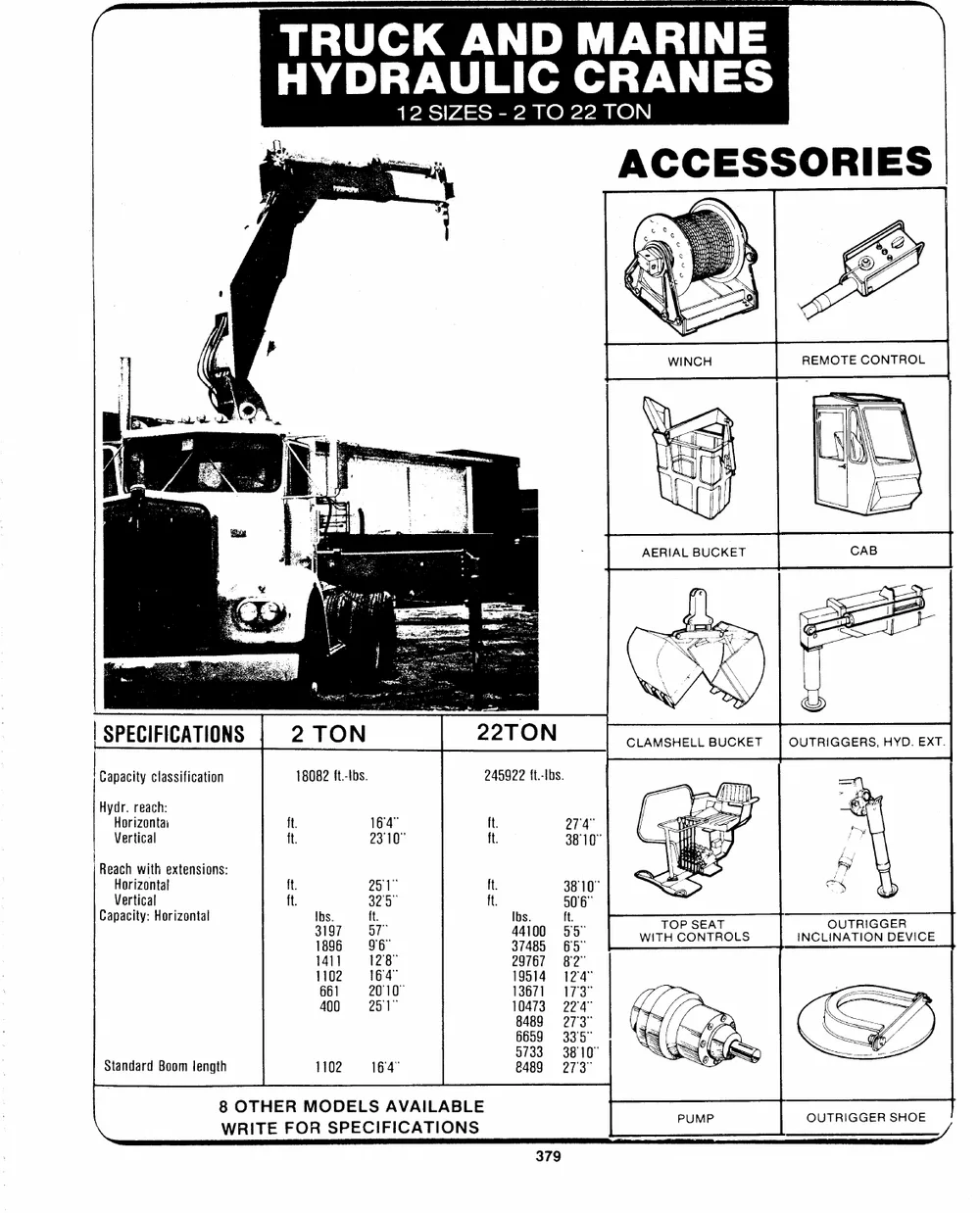
HYDRAULIC CRANES
12 SIZES - 2 TO 22 TON
SPECIFICATIONS 2 TON
Capacity classification 18082 ft.-Ibs. 245922 ft.-Ibs.
Hydr. reach: ft. 164� ft. 274�
Horizontai tt. 23 10� ft.
38�10"
Vertical
Reach with extensions: ft. 251" ft. 38�10"
ft. 325�
Horizontal Ibs. ft. ft. 90'6"
Vertical Ibs. ft. TOP SEAT OUTRIGGER
Capacity: Horizontal WITH CONTROLS INCLINATION DEVICE
3197 57" 44100 55�
Standard Boom length 1896 96� 37485 65" PUMP OUTRIGGER SHOE
1411 12:8" 29767 82"
1102 �164� 19514 124"
661 20�10" 13671 = =17�3"
400 201� 10473 22�4"
8489 273"
6659 335�
1102 164� 0733 = 3810"
&489 = 273�
8 OTHER MODELS AVAILABLE
\ WRITE FOR SPECIFICATIONS
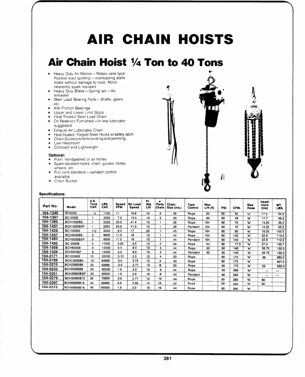
AIR CHAIN HOISTS
Air Chain Hoist 4 Ton to 40 Tons
Heavy Duty Air Motors --Rotary vane type �
Positive load spotting --overloading stalls
motor without damage to hoist. Motor
inherently spark resistant.
Heavy Duty Brake --Spring set--Air
released
Steel Load Bearing Parts --Shafts, gears,
etc.
e Anti-Friction Bearings
e Upper and Lower Limit Stops
e Heat Treated Steel Load Chain
e Oil Reservoir Furnished --In line lubricator
suggested
� Exhaust Air Lubricates Chain
� Heat treated, Forged Steel Hooks w/safety latch
@ Chain Guide prevents twisting and jamming
e Low Headroom
e Compact and Lightweight
Optional:
e Plain, handgeared or air trolley
e Spark resistant hooks, chain. guides, trolley
wheels, etc.
e Pull cord standard --pendant control
available
@ Chain Bucket
Specifications:
Pa. rt No. Model TCoAnPs. | CLABPS. | SFpPeMed |NoSpeLeodad| SLitfdt. P|aCrhatin Sie tins.) Cetrol tit(ft PS! | CFM. Hose r(ionsn) Bs.
104-1349 BC500B V2 1100 | 11 19.8 10 2 .25 Rope 82 90 42 Ya" 17.5 34.3
17.7
104-1367 BC10008 1 2200 7.5 13.5 10 2 30 Rope 82 90 49 %" 14.25 49.5
104-1385 1 28 %" 14.25 35.2
104-1401 BCH1000BS 1 2200 | 23.0 | 41.4 10 1 28 Rope 164 90 70 %" 18.25 35.2
104-1429 1 43 %" 22.8 102.5
104-1447 BCH1000BSP 1 2200 | 23.0 41.0 10 1 44 Pendant | 164 90 70 %" 22.8 112.2
104-1483 1 44 %" 27.5 112.2
BC1500BS 1%/ | 3300 9.5 17 20 Rope 164 90 80 26.75
104-1492 2 50 %" 135.7
104-1508 BCH3000BS 3 6600 | 11.5 16 10 2 44 Rope 164 90 140 %" 26.75 130.0
104-1526 2 39
104-0171 BCH3000BSP 3 6600 | 11.5 16 10 4 44 Pendant | 164 90 140 Ya" 130.0
104-0199 4 50 %" 39 283.0
104-0215 BC 5000B `5 11000 3.25 5.5 10 6 50 Rope 65 90 77.5 Ya" -- 407.0
104-0233 BCH60008 6 13200 5.5 8.0 10 8 50 Rope 82 90 140 %" _ 550.0
104-0251 BCH6000BP 8 44
104-0279 | 6 13200 5.5 8.0 10 12 44 Pendant | 82 90 140 %" 80 _
16 44 %" 80 _
104-0297 BC100008 10 22000 3.10 5.5 10 A4 Rope 90 175 Ya"
104-0313 16 Ya"
BCH12000B4 12 24000 3.0 3.75 10 44 Rope 90 175
BCH20000B6 20 40000 2.0 Rope 4"
2.77 10 90 175
BCH25000B8
25 50000 1.5 2.0 10 Rope 90 280
BCH25000B8SP| 25 50000 1.5 2.0 10 Pendant 90 280
|] BCH35000B12 | 35 70000 2.0 2.77 10 Rope 90 280
|8CH40000B12 | 40 80000 2.0 2.00 10 Rope 90 280
BCHS50000B16 | 50 100000 1.5 2.0 10 Rope 90 280
ELECTRIC CHAIN HOISTS
& END TRUCKS
Electric Chain Hoists
1% Ton to 20 Ton
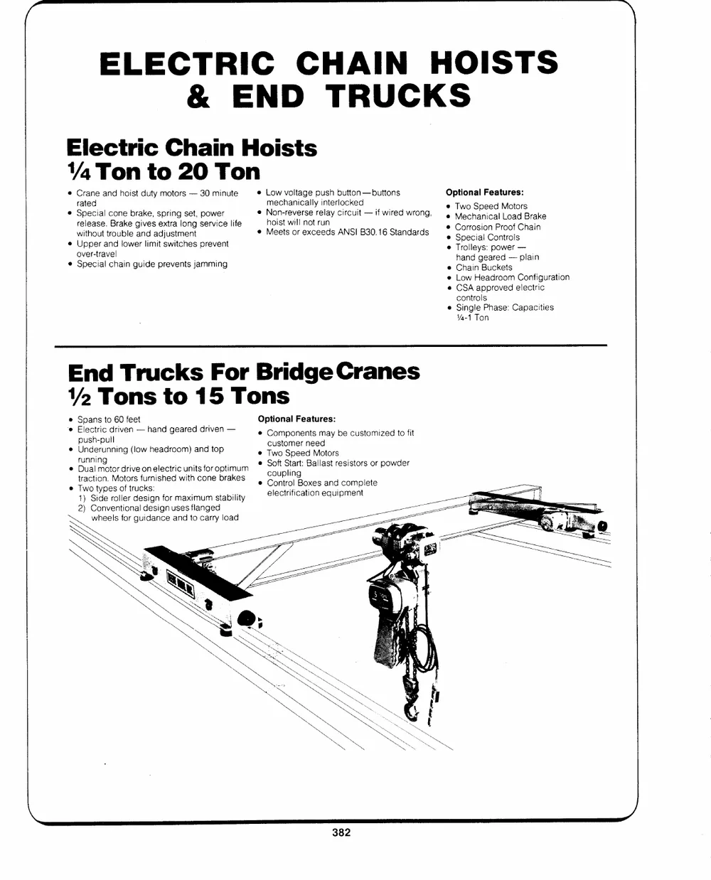
Crane and hoist duty motors -- 30 minute e Low voltage push button --buttons Optional Features:
rated mechanically interlocked
Special cone brake, spring set, power Two Speed Motors
release. Brake gives extra long service life e Non-reverse relay circuit -- if wired wrong, Mechanical Load Brake
without trouble and adjustment hoist will not run Corrosion Proof Chain
Special Controls
Upper and fower limit switches prevent e Meets or exceeds ANSI B30.16 Standards Trolleys: power --
over-travel hand geared -- plain
e Special chain guide prevents jamming Chain Buckets
Low Headroom Configuration
CSA approved electric
controls
Single Phase: Capacities
4-1 Ton
End Trucks For Bridge Cranes
2 Tons to 15 Tons
e Spans to 60 feet Optional Features:
`e Electric driven -- hand geared driven --
e Components may be customized to fit
push-pull customer need
Underunning (low headroom) and top
e Two Speed Motors
running e Soft Start: Ballast resistors or powder
Dual motor drive on electric units for optimum
traction. Motors furnished with cone brakes coupling
Two types of trucks: e Control Boxes and complete
1) Side roller design for maximum stability
2) Conventional design uses flanged electrification equipment
wheels for guidance and to carry load
ELECTRIC CHAIN HOISTS
& END TRUCKS
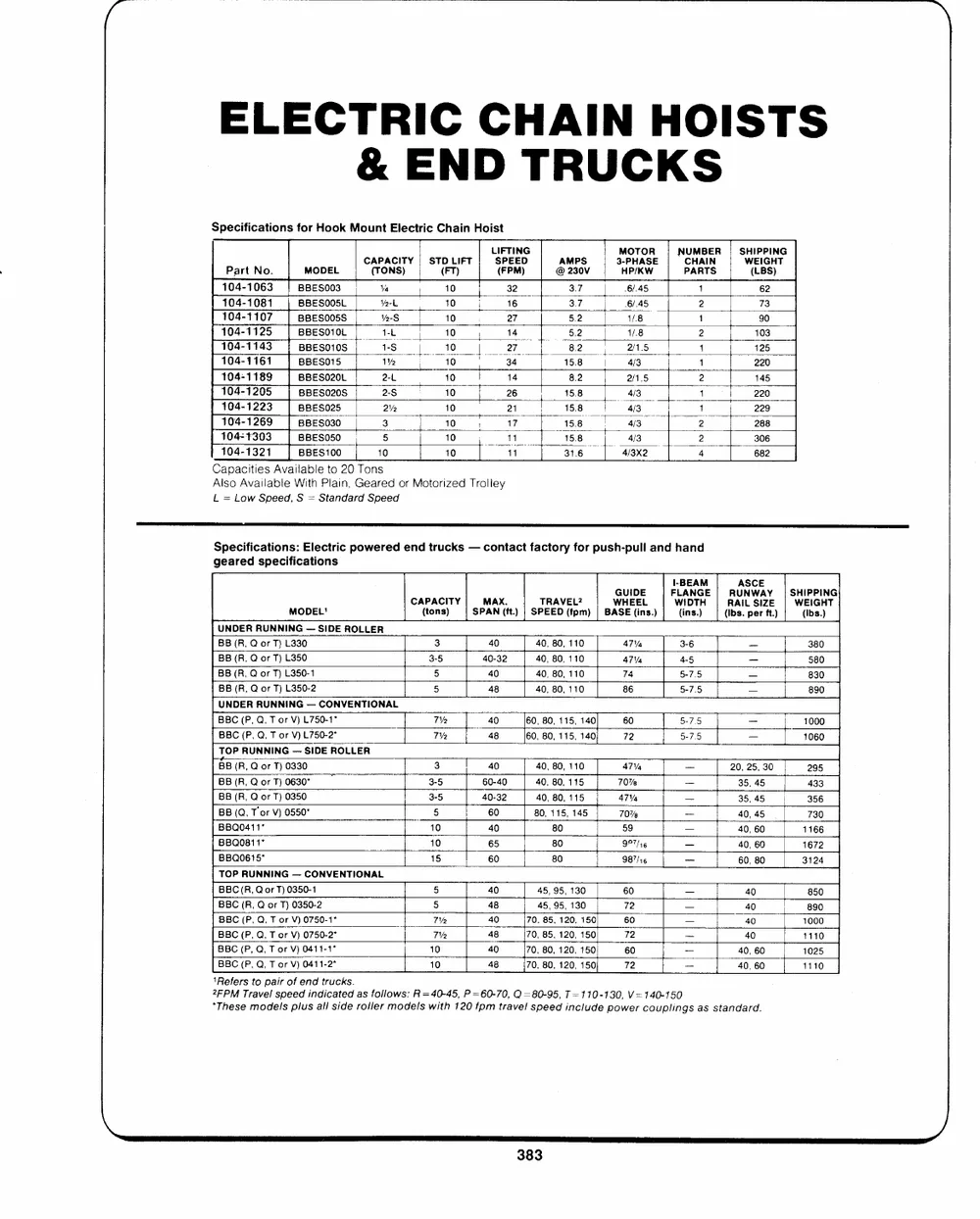
Specifications for Hook Mount Electric Chain Hoist
Part No. MODEL C(ATPOANCSI)TY | ST(OFLTI) FT | LSI(PFFTEPIMEN)DG @AM2P30SV 3MH-OPPT/HAKOSWRE| | NUPCAHMRABTIESNR| SWH(EILPIBPGSIH)NTG
104-1063 | BBESO03 Ya , 10 32 37 6/.45 1 62
104-1081 | BBESOOSL
Yt 10, 3.7 6/.45 2 73
104-1107 BBESO0SS v-S 10 27 5.2 1/.8 1 90
104-1125 | BBESO1OL tL to, 14 �| 582 1.8 2 103
104-1143 | BBESO10S rS | 10 | tw 1 125
104-1161 | BBESO15
1% | 10 | 34 15.8 4/3 1 220
104-1189 BBESO20L 2-L 10 14 8.2 2/1.5 2 145
104-1205 | sBEeso20S a ee 15.8 4/3 1 220
104-1223 | BBESO25 2% 10 15.8 4/3 1 229
104-1269 | BBESO30 3 10; 17 158 | 4/3 2 288
104-1303 BBES0S0 5 10 | 11 15.8 4/3 2 306
104-1321 | BBES100 10 Oe 31.6 | 4/3x2 4 682
Capacities Available to 20 Tons
Also Available With Plain, Geared or Motorized Trolley
L = Low Speed, S = Standard Speed
Specifications: Electric powered end trucks -- contact factory for push-pull and hand
geared specifications
MODEL' CA(PtAoCnsI)TY|| SPMAANX.(ft.) | SPTEREADVE(Lf?pm) | BAWGSHUEEIDE(iELns.) | FIWL-(IiABnDEsNT.AG)HME|||(RIRbAsUAI.NLSpCWeSErAIZYftE.)||SWHEI(IIPbPGs.IH)NTG
UNDER RUNNING -- SIDE ROLLER
BB (R, Q or T) L330 3 40 40, 80, 110 ATV 3-6 = 380
BB (R, Q or T) L350 3-5 40-32 40, 80, 110 47% 4-5 -- 580
BB (R, Q or T) L350-1 5 40 40, 80, 110 74 5-7.5 -- 830
BB (R, Q or T) L350-2 5 48 40, 80, 110 86 5-7.5 -- 890
UNDER RUNNING -- CONVENTIONAL
BBC (P, Q, T or V) L750-1" 7�2 40 60, 80, 115, 140 60 5-7.5 _ | 1000
5-75
BBC (P, Q, T or V)L750-2" V2 48 60, 80, 115, 140 72 -- | 1060
TOP RUNNING -- SIDE ROLLER 3 40 40, 80, 110 47% -- 20, 25, 30 295
BB (R, Q or T) 0330 3-5 60-40 40, 80, 115 70% -- 35, 45 433
BB(R, QorT) 0630"
BB (R, Q or T) 0350 3-5 40-32 40, 80, 115 47% -- 35, 45 356
BB (Q, Tor V) 0550"
5 60 80, 115, 145 70% ~ 40, 45 730
BBQ0411�
10 40 80 59 -- 40, 60 1166
BBQ0811*
BBQO615" 10 65 80 97/16 -- 40, 60 1672
60, 80 3124
TOP RUNNING -- CONVENTIONAL 15 60 80 987/16 _
BBC(R, Q or T) 0350-1 5 40 45, 95, 130 60 -- 40 850
BBC (R, Q or T) 0350-2 5
BBC (P, Q, T or V) 0750-1" Va 48 45, 95, 130 72 -- 40 890
BBC (P, Q, T or V) 0750-2" Va
BBC (P, Q, T or V) 0411-1" 10 40 70, 85, 120, 150 60 -- 40 4000
48 70, 85, 120, 150 72 -- 40 1110
40 70, 80, 120, 150 60 -- 40, 60 1025
BBC (P, Q, T or V) 0411-2* 10 48 70, 80, 120, 150 72 _ 40, 60 1110
`Refers to pair of end trucks.
2FPM Travel speed indicated as follows: R=40-45, P=60-70, Q =80-95, T=110-130, V= 140-150
"These models plus all side roller models with 120 fpm travel speed include power couplings as standard.
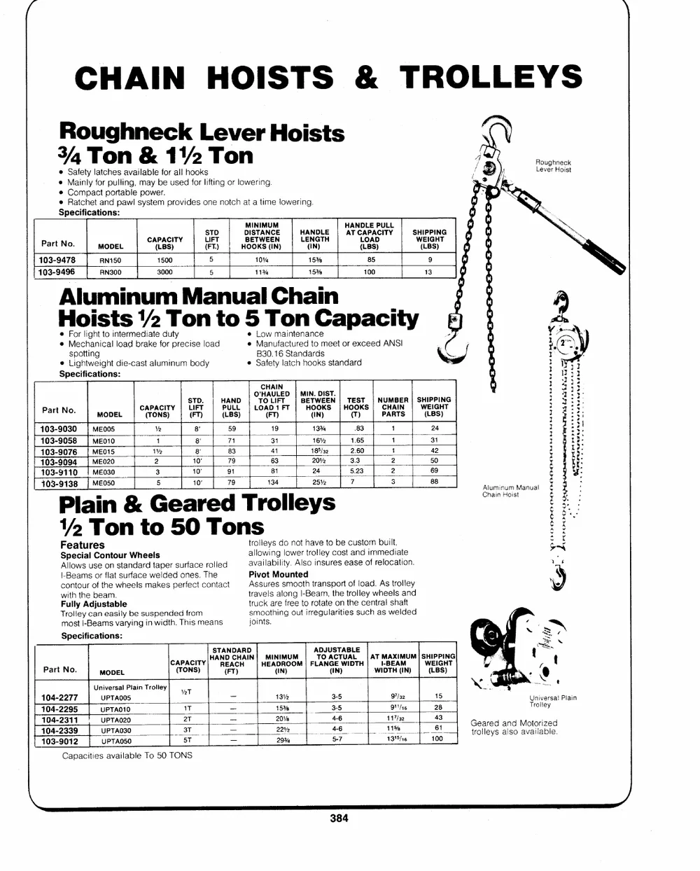
Roughneck Lever Hoists Roughneck
Lever Hoist
34, Ton & 11/2 Ton
@ Safety latches available for all hooks
e Mainly for pulling, may be used for lifting or lowering.
* Compact portable power.
e Ratchet and pawl system provides one notch at a time lowering.
Specifications:
Part NoO. MODEL CA(PLABCSI) TY (LSFITTF.DT) HDBMOIEIOSNTKTIWSAMENU(ECIMNNE) HLAE(NNINDG)LTEH HAATNCD(LALLOPBEAAS)DCPIUTLYL WSHE(IILPBGPSHI)NTG
103-9478 RN150 1500 5 10% 15% 85 9
t 103-9496 RN300 3000 5 11% 15% 100 13
Aluminum Manual Chain
Hoists 12 Ton to 5 Ton Capacity
e For light to intermediate duty e Low maintenance wee
\-- / �
@ Mspeocthtainngical load brake for precise load e MBa3n0u.f1a6cSttuarneddatrodsmeet or exceed ANSI 3
I c,
e Lightweight die-cast aluminum body e Safety latch hooks standard > Y rt
Specifications: CHAIN } a 22
Pos
Part No. MODEL CA(PTAONCSI)TY| SL(TIFDFT.)T HP(ALUBNLSDL) | OLT'OOHA(LAFDIUT1)FLFTETD|| | MBIEHNT(O.IWOND)EKISESTN.|| HT(OETOS)KTS|| NCUHMABIENR|| SWHEIPIPGIHNTG
PARTS (LBS) 1PPoas4t t.y3y::
8 59 19 13% 83 1 24 ; i fi
103-9030 MEO05 Ve
12 1 % 8180'"� 463113 1218056�/%232 231...63605 211 ; * :!
Plain & Geared Trolleys 111000333---999000957486 ||| MMMEEE00O211050 778139 354102 tt2 tbrehf:.
3 10 a1 81 24 5.23 2
110033--99111308 _|| MMEE0Os3o0 69 t yy:
= 8
8 10" 79 134 25% | 7 Le: CahlauimninHuoimstManual!2 ;
i es
�SFpee2actiaulrTeCosnotounr Whetelos 50 Tons E yity
atrlollolweiynsgdolonwoetr htraovleletyocbosetcaunsdtoimmmbeuidlit,ate 7a --~tYoe
Allows use on standard taper surface rolled availability. Also insures ease of relocation.
c|o-nBteoaumrsoofrtfhleatwshuereflascemwaekledsedperofneecst. cTohnetact APisvsoutreMsosumnotoetdh transport of joad. As trolley VeQ
with the beam. travels along I-Beam, the trolley wheels and ;~
Fully Adjustable truck are free to rotate on the centra! shaft
Trolley can easily be suspended from smoothing out irregularities such as welded =`
most I-Beams varying in width. This means joints.
Specifications: o--S *
Lt
STANDARD ADJUSTABLE
C(ATPAOCNIST)Y) HANR(DEFATC)CHHAIN| HMEIAN(DIINR)MOUOMM| FLTAONAG(ICENT)WUIADLTH|AWTIIMD-ATBXHEIA(MMINU)M| SWH(EILIPBPGSI)HNTG -@
Part No. MODEL
Universal Plain Trolley vat _ 13% 3-5 97/2 15 ~~. �
104-2277 UPTAOOS Universal Plain
1T -- 15% 3-5 o/s 28 Troiley
104-2295 UPTAO10
104-2311 UPTA020 2T -- 222029%%% | 546--76 11131%'75//3126 _6140130 Gtreoalrleeyds aalnsdo Maovatiolraibzleed.
110043--29303192 UUPPTTAAO03500 53TT =_
Capacities available To 50 TONS
\
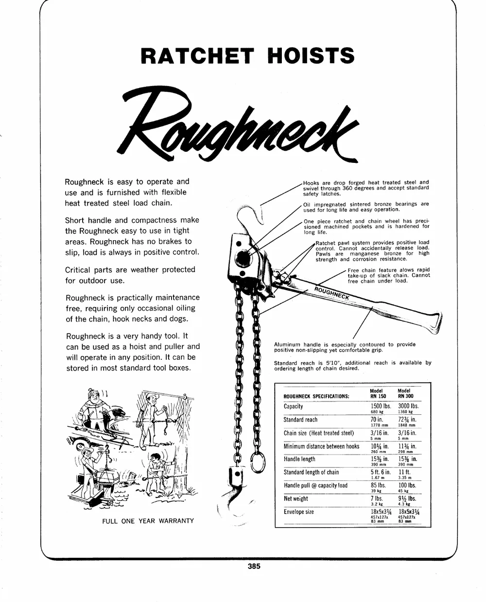
RATCHET HOISTS
Quglmeck
Roughneck is easy to operate and Hooks tahrreoudgrhop36f0ordgeegdreheesatandtreaactceedptstsetealndaanrdd
use and is furnished with flexible swivel
heat treated steel load chain. safety latches.
Short handle and compactness make
the Roughneck easy to use in tight gu � Oil impregnated sintered bronze bearings are
areas. Roughneck has no brakes to used for long life and easy operation.
slip, load is always in positive control.
Critical parts are weather protected One piece ratchet and chain wheel has preci-
for outdoor use. sioned machined pockets and is hardened for
Roughneck is practically maintenance long life.
free, requiring only occasional oiling
of the chain, hook necks and dogs. cRPoaantwtclrhsoel.tarpCeaawnlnmosatynsgtaaecncmiedsperenotvailbdlreyosnzrpeeolseiaftsoierve load
Roughneck is a very handy tool. It strength and corrosion resistance. load.
high
can be used as a hoist and puller and
Free chain feature alows rapid
will operate in any position. It can be take-up of slack chain. Cannot
stored in most standard tool boxes. free chain under load.
FULL ONE YEAR WARRANTY "ESaUGHNESe
Heme
Wy "i Aluminum handle is especially contoured to provide
positive non-slipping yet comfortable grip.
mm fy
Standard reach is 5'10", additional reach is available by
i Me ordering length of chain desired.
(naj
(iuae
Y Model Model
ry Hee:") ROUGHNECK SPECIFICATIONS:
RN 150 RN 300
(ft) Ww Capacity
tafe Standard reach 1500 Ibs. 3000 Ibs.
y TI Chain size (Heat treated steel)
Qo Minimum distance between hooks 680 kg 1360 kg
Handle jength
Standard length of chain 70 in. 7234 in.
Handle pull @ capacity load
Net weight 1778 mm 1848 mm
Envelope size
3/16 in. 3/16in.
5 mm 5 mm
10% in. 1134 in.
260 mm 298 mm
153% in. 153% in.
390 mm 390 mm
5ft.6in. 11 ft.
1.67 m 3.35 m
85 Ibs. 100 Ibs.
39 kg 45 kg
7 Ibs. 91 Ibs.
3.2 kg 4.3 kg
18x5x3%4 --:18x5x314
HOISTS
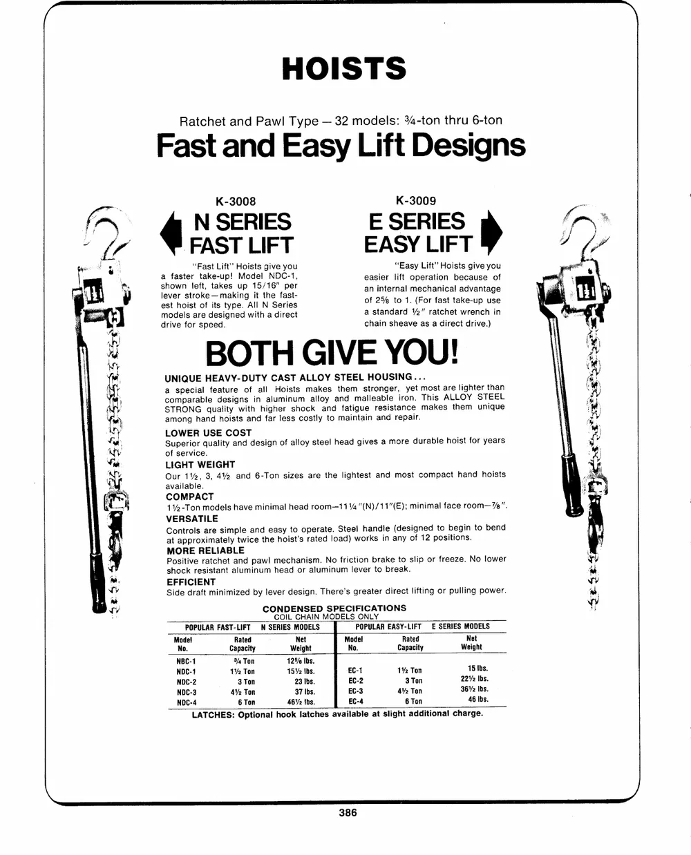
Ratchet and Pawl Type -- 32 models: 34-ton thru 6-ton
Fast and Easy Lift Designs
K-3008 K-3009
N SERIES E SERIES
FAST LIFT EASY LIFT
"Fast Lift' Hoists give you "Easy Lift" Hoists give you
a faster jake-up! Meee te" pet easier lift operation because of
slehvoewr nstlrefot,ke--tamkaeskiunpg it the " fapsetr- an i: nternal mechanic: al advantage
est hoist of its type. All N Series of 25 to 1. (For fast take-up use
models are designed with a direct a standard Y2" ratchet wrench in
"BOTH GIVE YOU! chain sheave as a direct drive.)
Pelt
oe
cSUaaomTNmsoRIppnOQeagcrNUiaGEahblalHnqefduEeadAalhetioVtusiyrYisetg-wsnDisotafUhniTdnahYllifaaglCrhHuAeolmreiSissTnsstushcmAoocLmskataLllklOyeoaYysntodSatmnTfhadaEietnEmimtgLaaulisetlnHreOroaaeUnbnsglSdeieIrs,rtNeiaGprnaoyc.niee.r.t..mmTohaisksteasrAeLtLhlOeiYgmhteSurnTitEqhEauLne x 2roeet
aaa = aati
LOWER USE COST years
of alloy steel head gives a more durable hoist for fey
Superior quality and design x
of service.
LIGHT WEIGHT
Our 1%, 3, 4% and 6-Ton sizes are the lightest and most compact hand hoists
available.
COMPACT have minimal head room--111% "(N)/11"(E); minimal face room--7%".
1�2-Ton models
VCatoEnRatprSpoArlTosxIiaLrmEeatseilmypltweicaendtheeashoyistto'sopreartaetde.loSatde)elwohraknsdlien (designed to begin to bend
any of 12 positions.
MORE RELIABLE mechanism. No friction brake to slip or freeze. No lower
Positive ratchet and pawl head or aluminum lever to break.
shock resistant aluminum
EFFICIENT by lever design. There's greater direct lifting or pulling power.
Side draft minimized
CONDENSED SPECIFICATIONS
COIL CHAIN MODELS ONLY
POPULAR FAST-LIFT N SERIES MODELS POPULAR EASY-LIFT � SERIES MODELS
Model Rated : Net Model Rated Net
No. Capacity Weight No. Capacity Weight
NBC-1 % Ton 125/ Ibs. EC-1 1�2 Ton 15 Ibs.
NDC-1 1% Ton 1572 Ibs. EC-2 3 Ton 222 Ibs.
NDC-2 EC-3 4�2 Ton 36% Ibs.
3 Ton 23 Ibs.
NDC-3 4% Ton 37 Ibs. 46 Ibs.
NOC-4 6 Ton 4612 Ibs. EC-4 6 Ton
LATCHES: Optional hook latches available at slight additional charge.
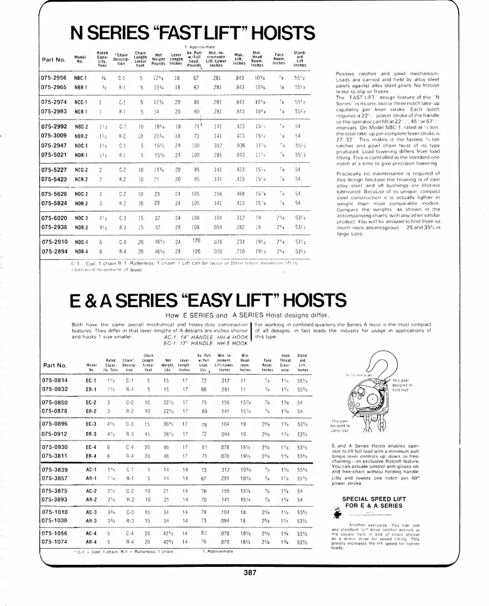
N SERIES "FAST LIFT" HOISTS
1. Approximate
Part No Model Rated D*eCshcarii-pn- Chain WeNiegtht LLeenvgetrh Av. Pull Min. In- LiMfatx,. Min. RFoaocme Stand-
. 0. Capa- tion Length Pounds Inches w/Full crementt Inches Head Inches ard
city, Lineal load, Lift/Lower Room,
Tons Pounds Inches Lift
Feet inches Inches
075-2956 NBC-1 34 C-1 5 125% 18 67 281 843 105% 1% 5 542 PLoosaidtsiveareractacrhreited and hpealwdl bymeacllhoaynistseme.l
075-2965 NBR-1
5ly and
pawls against alloy steel gears. No friction
34 R-] 5 13% 18 67 281 843 105% 8 wn
brake to slip or freeze
075-2974 NCC-1 1 C-1 5 1234 20 80 28] 843 10% 78 5542 The "FAST LIFT' design feature of the "'N
Series' isits one, twoor three notch take-up
capability per lever stroke. Each notch
075-2983 NCR-1 l Rei 5 14 20 80. 281 843 1053 15 5545 requires a 22'>" power stroke of the handie
!
714\ so the operator canlift at 22'2",45�%or67!>
075-2992 NBC-2 Lh C-2 l 18538 18 141 423 15a 8 54 intervals. On Model NBC-1, rated at 34-ton,
141 423 15la 3 54 the total tTahkies-upmapkerescomitpltehtee lever stroke Is
075-3009 NBR-2 TL, R.2 10 234 18 7] , , 27 32�. fastest 34-ton
a - -
075-2947 NODC-1 lhe "1 5 15%, 24 100 312 936 tl 78 5512 ratchet and paw! chain hoist of its type
produced. Load towering differs from load
075-5021 ---NDR-1 1h Rel 5 15%. 24 100 28] 843 bbe 5 9512
lifting. This is controlled to the standard one
notch at a time to give precision lowering
075-5227 ~=NCC-2 2 C-2 10 1933 20 85 141 423 15hy te 5A Practically no maintenance is required of
075-5423 = NCR-2 2 R-2 10 2] 20 85 14) A23 15'4 "8 54 this design because the housing is of cast
075-5628 NDC-2 78 54 alloy steel and all bushings are lifetime
3 C.2 10 23 24 105 156 AGS 1578
075-5824 NDR-2 7% 54 lubricated. Because of its unique, compact
steel construction it is actually lighter in
3 R-2 1 23 24 105 141 423 15%
weight than most comparable models
Compare the weights, as shown in the
075-6020 NDC3 42 C3 15 37 24 �108-104 812 25g 5312 aprcocdoumcptanYyoiungwicllhabrets,amwaitzhedantyo oftihnedr stihmeimlasro
075-2938 NDR-3 Aly R-3 15 37 24 108 094 282 19 258 5312 much more advantageous 25 and 35% in
large sizes
075-2910 NDC4 6 C4 20 46% 2g s*120--Scg 234 1912, 2g 53 h2
R-4 20 462 24
075-2894 NDR-4 6 120 .070 210 19! 238 9312
C-1. Co. 1 chain R-1:Rollerless, 1 chain 7 Lift can be twice or three times minimum ft by
mereased movement of lever
E & A SERIES "EASY LIFT" HOISTS
How E SERIES and A SERIES Hoist designs differ.
Both have the same overall mechanical and heavy-duty construction For working in confined quarters the Series A hoist is the most compact
of all designs; in fact leads the industry for usage in applications of
features. They differ tn that lever lengths of A designs are inches shorter this type
and hooks 1 size smailer AC-1: 14" HANDLE. HH-4 HOOK|
EC-1: 17" HANDLE. HH-5 HOOK ~
Chain Ay. Pull Min. fn- Min. Hook Stand-
Length, w/Full crement Head- ard
Part No. Model Rated Chain* Lineal Net Lever load. Lift/Lower, roam, Face Throat Lift.
075-0814 No. Capac- Descrip- Weight. Length. Inches Room, = Ciear-
EC-1 ity, Tons Feet inches Lbs. | Inches Inches ance Inches
075-0832 tion Lbs.
ERT
Ru fection brake
1M. C-1 5 15 17 72 312 14 Ur) 14 55 V2 This paw!
oi Ri 5 15 17 66 281 41 Yo Va 55%
hold load designed to
075-0850 EC-2 3 C-2 16 22V2 17 75 156 157s %s 1% �8654
075-0878
ER-2 3 R-2 10 22V2 17 69 141 15%s Ye 1%. 54
075-0896
EC-3 4V2 C-3 15 36V2 17 78 104 19 25s 15/4 532 dTehsiisgnpeadw!to
075-0912
ER-3 4% �=O R315 8BMz2s1T:--s("`a?#�+*#OCOAO1G 258 1% = �53% sory d
075-0930 EC-4 6 C-4 20 46 17 81 078 19% 2% 1% 5B Ve E and A Series Hoists enables oper-
075-3811
ER-4 6 R-4 20 46 17 75 070 19%, 25/8 17g 532 ator to lift full load with a minimum pull.
Single lever controls up, down. or free-
chaining--an exclusive Ratcliff feature.
075-3839 ACT 1% C1 5 14 y :
075-3857 14 73 312 10% % 1% 55% and freweith-ouchoh lditag hiandnle
AR-1 1 Ma R-1 5 14 14 67 .281 10%. %e 1�e 55% Lifts and lowers one notch per 60�
power stroke.
075-3875 AC-2 2V2 C-2 10 24 14 76 156 15% We 14 54
075-3893
AR-2 2V2 R-2 10 21 14 70 141 15% Ve 1% 54 SPECIAL SPEED LIFT
075-1010 14 104 18 25/8 1�2 532 FOR E & A SERIES
075-1038 AC-3 3%4 C-3 15 34 79 -4 we
075-1056 AR-3 33/4 R-3 15 34 14 73 094 18 27/6 1Y%. 53 %2 Another exclusive: You can use
075-1074 AC-4 5 C-4 20, 42% 14. B2COTBSS1BY2S HASH the sqtaunadraerhdolve2"dirn iend rof hchain senhcehavie
\ AR-A 5 R4 20 42% 1478 --COT1B Ye He 1% �BBY greatly increases the lift speed torlighte:
*C-1 = Coil, 1 chain; R-1 = Rolierless, 1 chain. 1. Approximate loads.
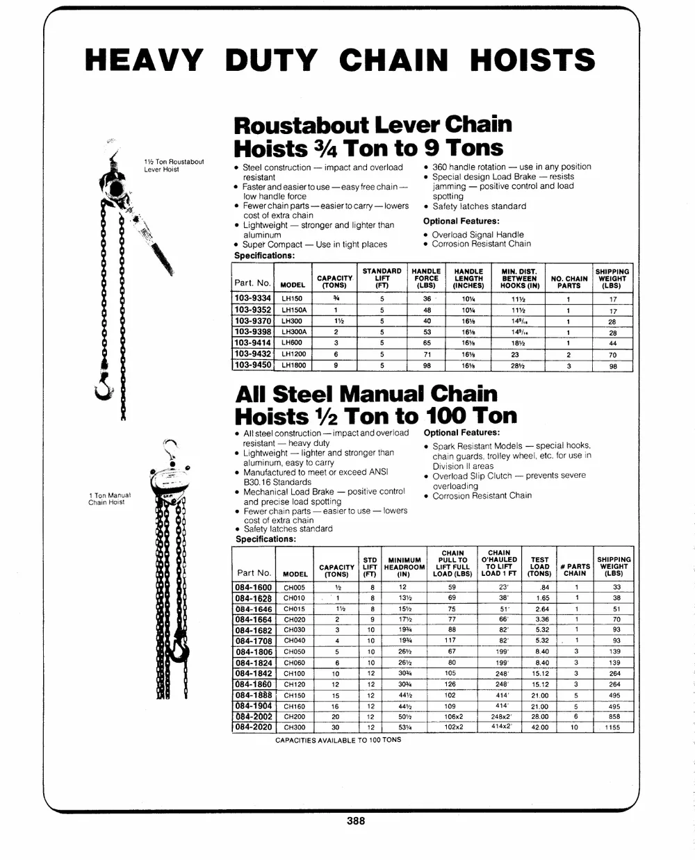
HEAVY DUTY CHAIN HOISTS
1% Ton Roustabout Roustabout Lever Chain
Hoists 34 Ton to 9 Tons
Lever Hoist e Steel construction -- impact and overload e 360 handle rotation -- use in any position
e Special design Load Brake -- resists
Ps resistant
mo e Faster and easier to use -- easy free chain -- jamming --positive control and load
spotting
"eS low handle force e Safety latches standard
e Fewer chain parts -- easietro carry -- lowers
q Optional! Features:
cost of extra chain
&i e Lightweight -- stronger and lighter than @ Overload Signal Handle
� Corrosion Resistant Chain
1 Ton Manual aluminum
Chain Hoist � Super Compact -- Use in tight places
Specifications:
STANDARD | HANDLE | HANDLE MIN. DIST. SHIPPING
Part. No.| mone | Wawa"| ten | CESt| ameses) | AbGRGIEy| MOCHA| W(ELIBGS)HT
103-9334| LH150 % 5 36� 10% 11% 1 17
103-9352] LH150A 1 5 48 10% 11% 1 17
103-9370 {| LH300 1% 5 40 16% 149h. 1 28
103-9398| LH300A 2 5 53 16% 14%). 1 28
103-9414| LH600 3 5 65 16% 18% 1 44
103-9432) LH1200 6 5 71 16% 23 2 70
103-9450; LH1800 9 5 98 16% 28% 3 98
All Steel Manual Chain
Hoists 1/2 Ton to 100 Ton
e Allsteel construction----impactandoverioad Optional Features:
resistant --heavy duty e cShpaairnk gRueasridsst,anttroMloledyewlhsee--l,septecc.iaflorhuosoeksi,n
� Lightweight lighter and stronger than e ODivwvetirsliooaneIIaSlriepaCslutch -- prevents severe
e Corrosion Resistant Chain
e aM8la3un0mu.if1na6ucSmtt,uareneaddastryodtsmoeceatrroyr exceed ANSI
� Mechanical Load Brake -- positive control
and precise load spotting
e Fewer chain parts -- easier to use -- lowers
cost of extra chain
e Safety latches standard
Specifications:
CHAIN CHAIN SHIPPING
STD | MINIMUM PULLTO | O'HAULED | TEST WEIGHT
CAPACITY| LIFT |HEADROOM| LIFTFULL | TO LIFT LOAD | #PARTS|
Part No. | MODEL (TONS) | (FT) (IN) LOAD (LBS) |LOAD 1FT| (TONS) | CHAIN (LBS)
084-1600| CHO005 Ve 8 12 59 23' 84 1 33
4 8 13% 38 1.65 1 38
084-1628| CHo10 69
084-1646| CHo15 1% 8 15�2 75 51' 2.64 1 51
084-1664| CHO020 2 9 17% 88 66" 3.36 1 70
084-1682 | CHO30 3 10 19% 117 82' 5.32 1 93
084-1708| CH040
4 10 19% 67 82" 5.32 1 93
084-1806| CH050 5 10 2612 199� 8.40 3 139
084-1824| CHO06O 6 10 26% 105 199� 8.40 3 139
084-1842| CH100 10 12 30% 126 248' 15.12 3 264
084-1860| CH120 12 12 30% 102 248' 15.12 3 264
084-1888 ; CH150 15 12 444% 414' 21.00 5 495
084-1904 | cHi60 16 12 44% 414 21.00 5 489558
20 12 50%2 106x2 248x2' 28.00 6
084-2002| CH200
30 12 53Vs 102x2 414x2' 42.00 10 . 1155
084-2020| CH300
CAPACITIES AVAILABLE TO 100 TONS
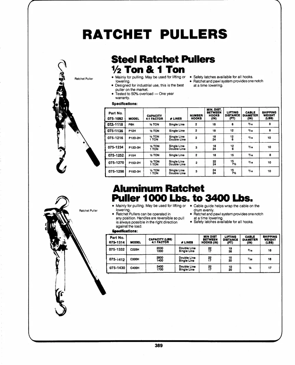
RATCHET PULLERS
Steel Ratchet Pullers
2 Ton & 1 Ton
@ Mainly for pulling. May be used for lifting or e Safety latches available for all hooks.
Ratchet Puller lowering. � Ratchet and pawl system provides one notch
e Designed for industrial use, this is the best at a time lowering.
puller on the market.
� Tested to 50% overload -- One year
warranty.
Specifications:
Part No. MIN. DIST. ,
NHUOMOBKESR | BHE(OTIWON)EKESN||DLIIS(FTFTTAI)NNCGE| | DICAA(MIBENTL)EER!| SWHE(ILIPBPGSIH)NTG
075-1092 | MODEL | 4C:A1PFAACCITTOYR | # LINES
075-1118| P�6H % TON Single Line 2 18 6 ig 8
|075-1136| P12H 2 TON Single Line 2 18 12 he 8
075-. 1216| P12D-. 2H �{2TTOONN | SDionvgblleeLLiinnee 2 P1y8 162 3/16 10
| 075-- 1234| P12D-3H {v2TTOONN DSionugblleeLLiinnee 3 2148 1�2 She 10
075-1252| pisH Ye TON Single Line 2 18 15 She 8
075-. 1270| P15D-. 2H %TOTONN DSionvgbllee LLiinnee 2 3242 175%, 3Ne 10
075-. 1298| P15D-3H 2{TTOONN DSionaglieeLLiinnee 3 324 4 15Me 3 16 10
Aluminum Ratchet
Puller 1000 Lbs. to 3400 Lbs.
@ Mainly for pulling. May be used for lifting or � Cable guide helps wrap the cable on the
Ratchet Puller lowering. drum evenly.
e Ratch�t Pulters can be operated in e Ratchet and pawl system provides one notch
any position. Handles are reversible so pull at a time lowering.
is always possible in the right direction
against the load. e Safety latches available for all hooks.
Specifications:
Part No. CA4P:1ACFIATCYTO(RLBS) #LINES | HB`OMEOIKTNSWD(EIISNT) | DLIIS(FTFTTAI)NNCGE | | DICAA(MIBNE)LTEER|| SWH(EILIPBPGSI)HNTG
075-1314 | MODEL 21000000 DSionugblleeLLiinnee 2172 | 3189
075-J 1332| c225H 0 16
075-1412| C300H 21840000 SDionugblleeLLiinnee 2127 3105 "Isa 6
075-. 1430| C400H 31470000 DSionugblleeLLiinnee 2172 2100 Me 7