Full chapter text (extracted from the original PDF)
Verbatim text extracted from the original chapter PDF (1940–). The original catalog is in English; spec tables may render imperfectly — the PDF remains the authoritative source.
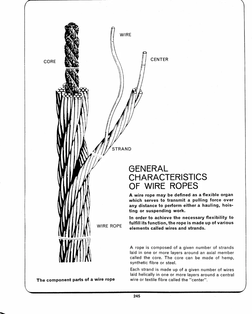
CORE CENTER
STRAND
\ \ WIRE ROPE GENERAL
t \ CHARACTERISTICS
OF WIRE ROPES
!
T/T |! A wire rope may be defined as a flexible organ
which serves to transmit a pulling force over
\ any distance to perform either a hauling, hois-
ting or suspending work.
In order to achieve the necessary flexibility to
fulfill its function, the rope is made up of various
elements called wires and strands.
\ The component parts of a wire rope A rope is composed of a given number of strands
laid in one or more layers around an axial member
called the core. The core can be made of hemp,
synthetic fibre or steel.
Each strand is made up of a given number of wires
laid helically in one or more layers around a central
wire or textile fibre called the "'center''.
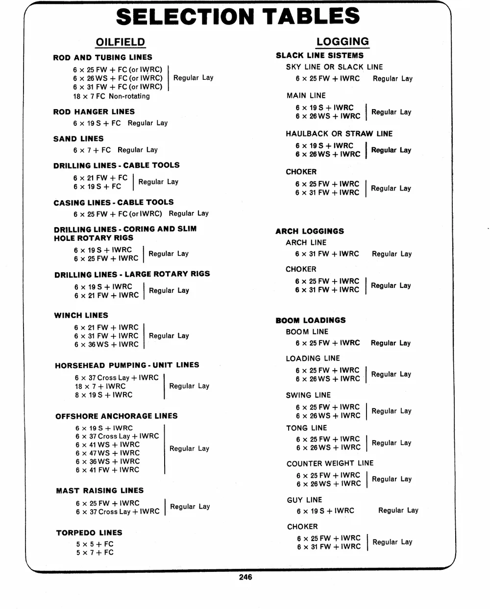
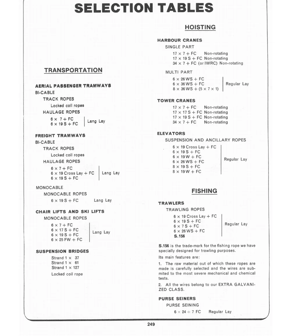
SELECTION TABLES
OILFIELD Regular Lay LOGGING
ROD AND TUBING LINES SLACK LINE SISTEMS
6 x 25 FW + FC (or IWRC)
SKY LINE OR SLACK LINE
6 x 26WS + FC (or IWRC) 6 x 22FW+IWRC ~~ Regular Lay
6 x 31 FW + FC (or IWRC) MAIN LINE
18 x 7 FC Non-rotating
ROD HANGER LINES 6x 19S + IWRC Reqular L.
6x19S+FC Regular Lay 6 x 22WS +IweRc| "estar bay
SAND LINES HAULBACK OR STRAW LINE
6x 7+ FC Regular Lay
66 xx 2196SWS+ +I1WIRwCrRc| Resular Lay
DRILLING LINES - CABLE TOOLS CHOKER
66xx i291s+FFWcF+C | Regular Lay 66 xx 3251FFWW++iIIwWrR\Cc| Regular Lay
CASING LINES - CABLE TOOLS ARCH LOGGINGS Regular Lay
6 x 25 FW + FC (orlWRC) Regular Lay ARCH LINE
6 x 31 FW + IWRC
DRILLING LINES - CORING AND SLIM
HOLE ROTARY RIGS
66xx 21 5 FW+ 9 I+WS IRwCec| Regular Lay
DRILLING LINES - LARGE ROTARY RIGS CHOKER
6x 19 +IWS RC Regular Lay 66xx 3251FFWW++IwIrWRRcC| Regular Lay
6 x 21 F + IW WRC
WINCH LINES Regular Lay BOOM LOADINGS Regular Lay
BOOM LINE
6 x 21 FW + IWRC 6x 25FW+IWRC
6 x 31 FW + IWRC
6 x 36WS + IWRC
HORSEHEAD PUMPING - UNIT LINES LOADING LINE
6 x 37 Cross Lay + IWRC Regular Lay 66 xx 2256FWWS ++ IIWWRRCC) Regular Lay
18 x 7+ IWRC
8 x 19S + IWRC SWING LINE
OFFSHORE ANCHORAGE LINES 6 x 25 FW +1IWRC Regular Lay
Regular Lay
6x 19S + IWRC Regular Lay 6 x 26WS + IWRC
6 x 37 Cross Lay + IWRC
TONG LINE
66 xx 4471WWSS ++ IIWWRRCC 6 x 25 FW + IWRC
6 x 26WS + IWRC
6 x 36WS + IWRC
6 x 41 FW + IWRC COUNTER WEIGHT LINE
MAST RAISING LINES 66 xx 2256F WS++IW IWwRRCc| Regular Lay
66 xx 3275 CFrWos+s IWRC Lay + IWRC Regular Lay GUY LINE Reguiar Lay
6 x 19S + IWRC
TORPEDO LINES CHOKER
5x 5+FC 66 xx 2315 FFWW ++IIWWRRCC Regular Lay
5x 7+ FC
TS
NN
com W.J. KEATING LIMITED
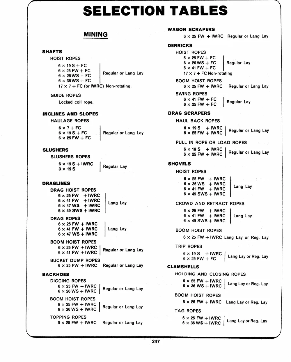
SELECTION TABLES
MINING WAGON SCRAPERS
6 x 25 FW +!WRC Regular or Lang Lay
DERRICKS
SHAFTS HOIST ROPES
HOIST ROPES 6 x 25FW + FC
6x19S+FC 6 x 26WS + FC Regular Lay
6 x 25 FW + FC 6 x 41 FW + FC
6 x 26WS + FC
Regular or Lang Lay 17 x 7+ FC Non-rotating
6 x 36WS + FC BOOM HOIST ROPES
6 x 25 FW +1IWRC
17 x 7+ FC (or IWRC) Non-rotating. Regular or Lang Lay
GUIDE ROPES SWING ROPES Regular Lay
Locked coil rope.
6 x 41 FW + FC
6 x 25 FW + FC
INCLINES AND SLOPES Regular or Lang Lay DRAG SCRAPERS Regular or Lang Lay
HAULAGE ROPES HAUL BACK ROPES
6x 7+ FC 6x19S +IWRC
6x19S+FC 6 x 25+F IWW RC
6 x 25 FW + FC
PULL IN ROPE OR LOAD ROPES
SLUSHERS 6x19S +IWRC |. Lang L
SLUSHERS ROPES 6 x 25 F +IW WRC | "eguiar or Lang Lay
63xx 1 19S 9 +IWS RC
Regular Lay SHOVELS
DRAGLINES HOIST ROPES Lang Lay
DRAG HOIST ROPES 6x 25FW +IWRC
6x 25FW +IWRC 6x 36WS +IWRC
6x 41 FW +IWRC 6x 414FW +IWRC
6x 47WS + IWRC 6 x 49 SWS + IWRC
6 x 49 SWS + IWRC
Lang Lay CROWD AND RETRACT ROPES
DRAG ROPES 6x 25FW +IWRC Lang Lay
6x 414 FW +IWRC
6 x 25 FW + IWRC 6 x 49 SWS + IWRC
6 x 41 FW + IWRC
6 x 47 WS + IWRC Lang Lay BOOM HOIST ROPES
6 x 25 FW + IWRC Lang Lay or Reg. Lay
BOOM HOIST ROPES Regular or Lang Lay TRIP ROPES
6 x 25 FW + IWRC 6x19S +IWRC Lang Lay or Reg. Lay
6 x 41 FW +1WRC 6 x 25 FW + FC
BUCKET DUMP ROPES CLAMSHELLS
6 x 25 FW +IWRC_ Regular or Lang Lay
BACKHOES HOLDING AND CLOSING ROPES
DIGGING ROPES
6 x 25 FW + IWRC 6 x 25 FW + IWRC Lang Lay or Reg. Lay
6 x 26WS + IWRC 6 x 36WS + IWRC
Regular or Lang Lay
BOOM HOIST ROPES Regular or Lang Lay BOOM HOIST ROPES Lang Lay or Reg. Lay
6 x 25 FW +1WRC Regular or Lang Lay 6 x 25 FW +IWRC
6 x 26WS + IWRC
TAG ROPES Lang Lay or Reg. Lay
TOPPING ROPES
6 x 25 FW +IWRC_ 6 x 25 FW + IWRC
6 x 36 WS + IWRC
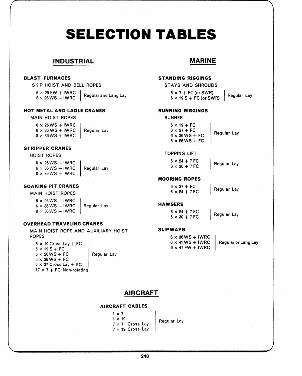
SELECTION TABLES
INDUSTRIAL MARINE
BLAST FURNACES STANDING RIGGINGS
SKIP HOIST AND BELL ROPES STAYS AND SHROUDS
66 xx 2256FWSW ++ IIWWRRCC Regular and Lang Lay 66xx 719+S F-C+F(oCr(SoWrRS)WR) | Regular Lay
HOT METAL AND LADLE CRANES RUNNING RIGGINGS
MAIN HOIST ROPES RUNNER
6 x 26WS + IWRC Regular Lay 6 x 19+ FC Regular Lay
6 x 36 WS + IWRC 6 x 37+ FC
8 x 36WS + IWRC 6 x 86 WS + FC
6 x 26+ WFS C
STRIPPER CRANES Regular Lay TOPPING LIFT | Regular Lay
HOIST ROPES 66 xx 28044++77FFCC
6 x 26WS + IWRC
6 x 36WS + IWRC
8 x 36WS + IWRC
SOAKING PIT CRANES MOORING ROPES | Regular Lay
MAIN HOIST ROPES 66 xx 23474+7FFCC
6 x 26WS + IWRC Regular Lay HAWSERS
6 x 36WS + IWRC
8 x 36WS + IWRC 66xx 23404+77FFCC | Regular Lay
OVERHEAD TRAVELING CRANES
MAIN HOIST ROPE AND AUXILIARY HOIST SLIPWAYS
ROPES
6 x 36WS + IWRC
6 x 19 Cross Lay + FC 6 x 414 WS + IWRC Regular or Lang Lay
6x 19S +FC 6 x 41 F + IW WRC.
6 x 26WS + FC
6 x 36WS + FC Regular Lay
6 x 37 Cross Lay + FC
17 x 7+ FC Non-rotating
AIRCRAFT
AIRCRAFT CABLES Regular Lay
1x7
41x 19
7x7 Cross Lay
7x 19 Cross Lay
go W.J. KEATING LIMITED
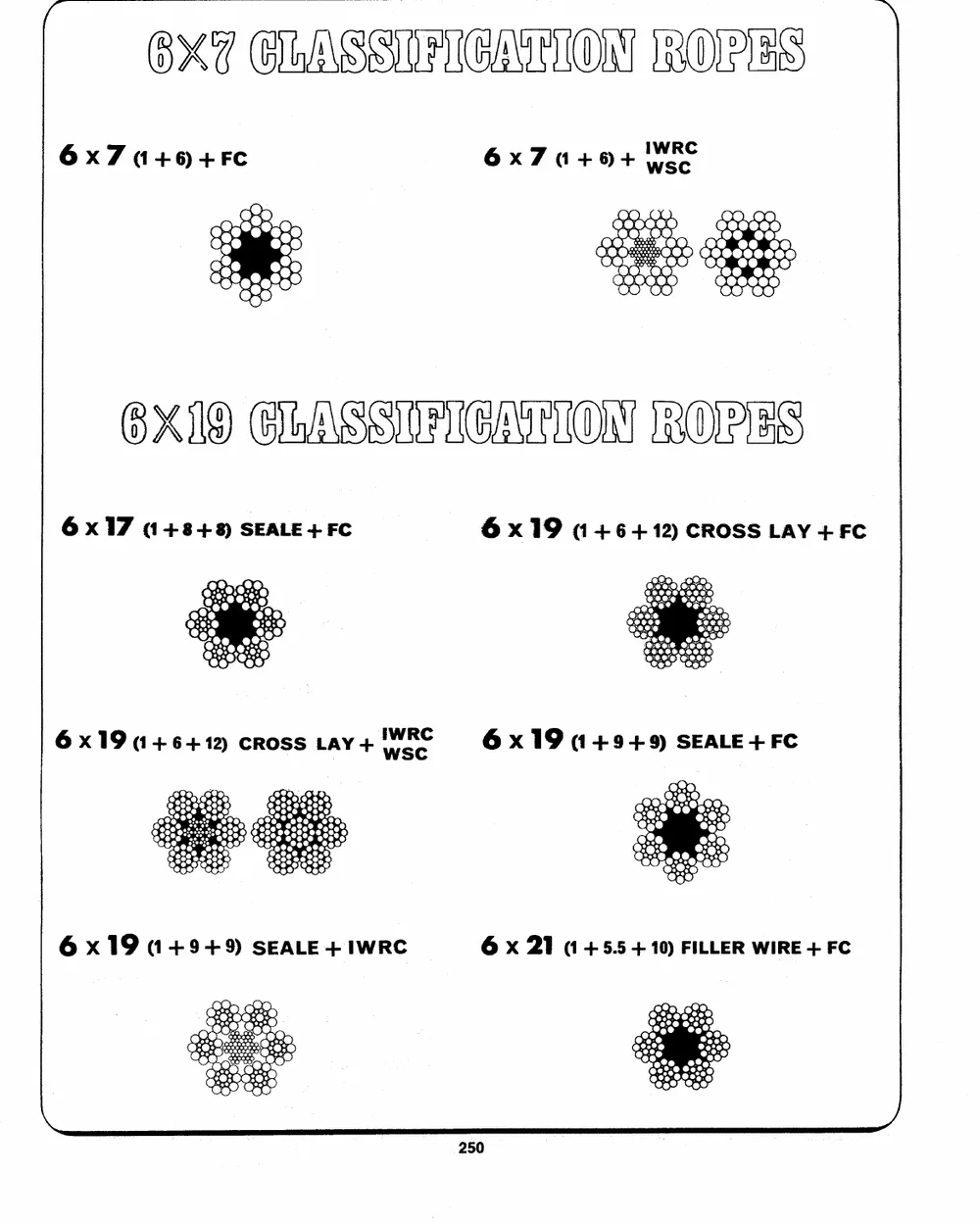
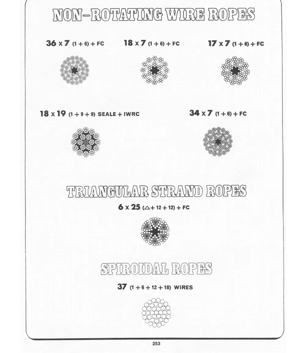
BX CASS FUGALUOM ROLE Bs
6x7 (1+6+FC 6x70+68+ IwWoReC
OISECIASSIBICATONSRORE'S
6 x17 (14848) SEALE+FC 6 x19 (146412) CROSS LAY+FC
6 x 19 (14.6412) CROSS LA+Y wee 6 x 19 (14945) SEALE +FC
6 x 19 (14949) SEALE + IWRC 6 x 21 (1 +5.5 + 10) FILLER WIRE + FC
=> xLu< _<S and=err>
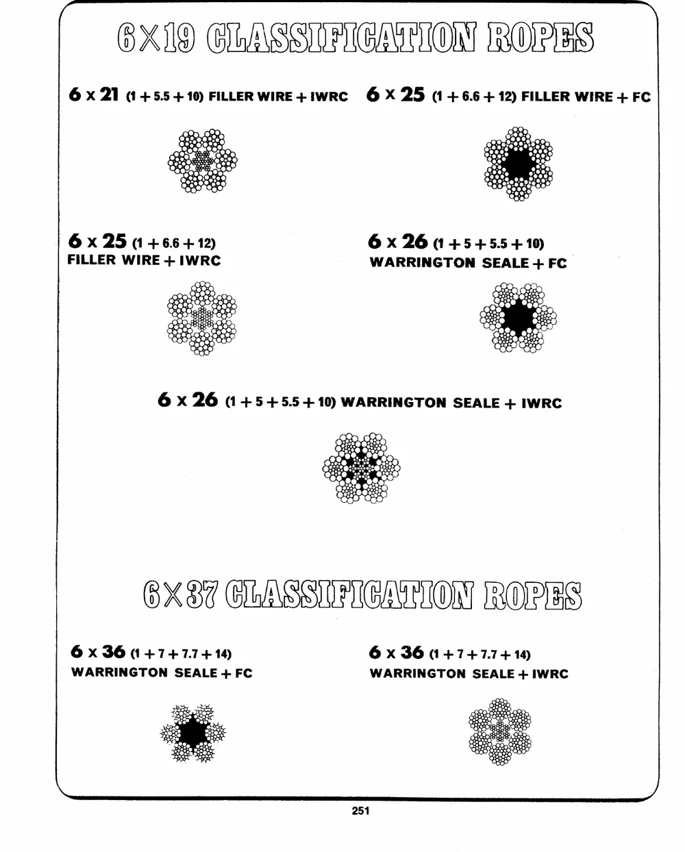
( @XAD GHASSOREATTOR RORES ~
6 x 21 (1 4+5.5 +10) FILLER WIRE+iwRe 6 X 25 (1+ 6.6 + 12) FILLER WIRE + FC
| 6x 25 (1 +6+16 2) 6 x 26 (14-5 +5.5 +10).
FILLER WIRE + IWRC WARRINGTON SEALE + FC
6 x 26 (14545.54 10) WARRINGTON SEALE + IWRC
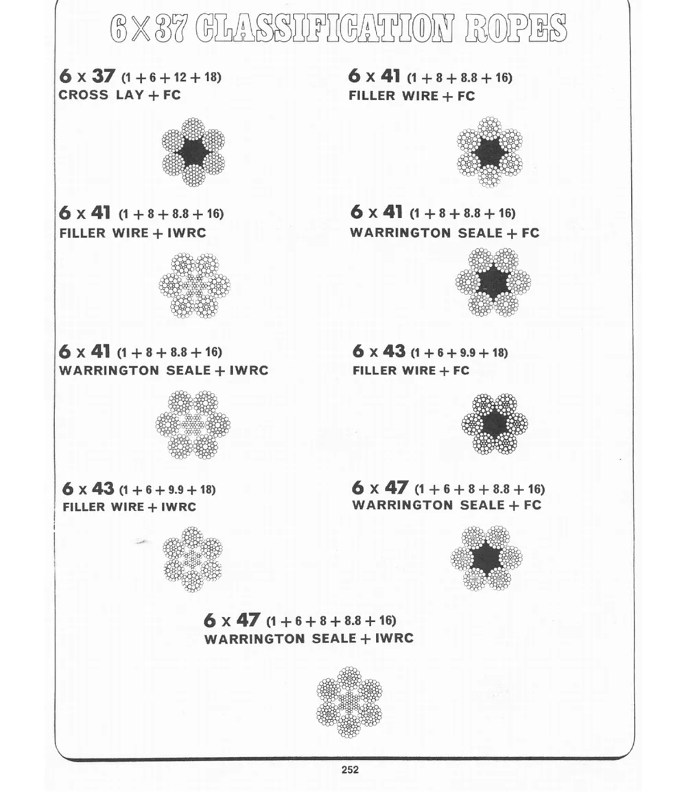
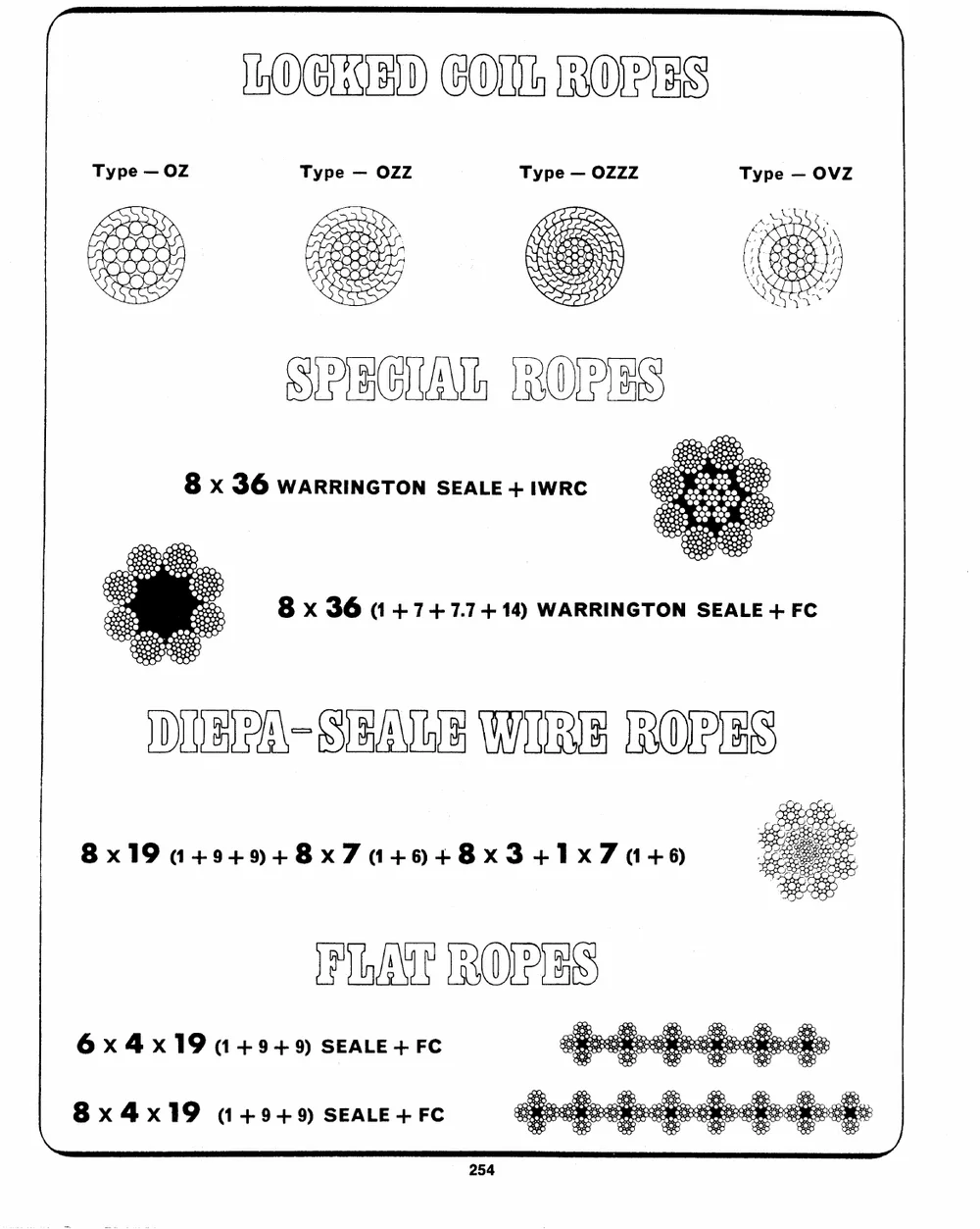
OSECLAS SUBIGATIONSRORE'S
6 x 36 (1474+ 7.7414 6 x 36 (14747.74 14)
WARRINGTON SEALE + FC WARRINGTON SEALE + IWRC
8x19 449494+8x704+6594+8x341x71+6)
BGATRORES
6x4x19 14+9+9) SEALE+FC
8x4x19 (49+9) SEALE+FC
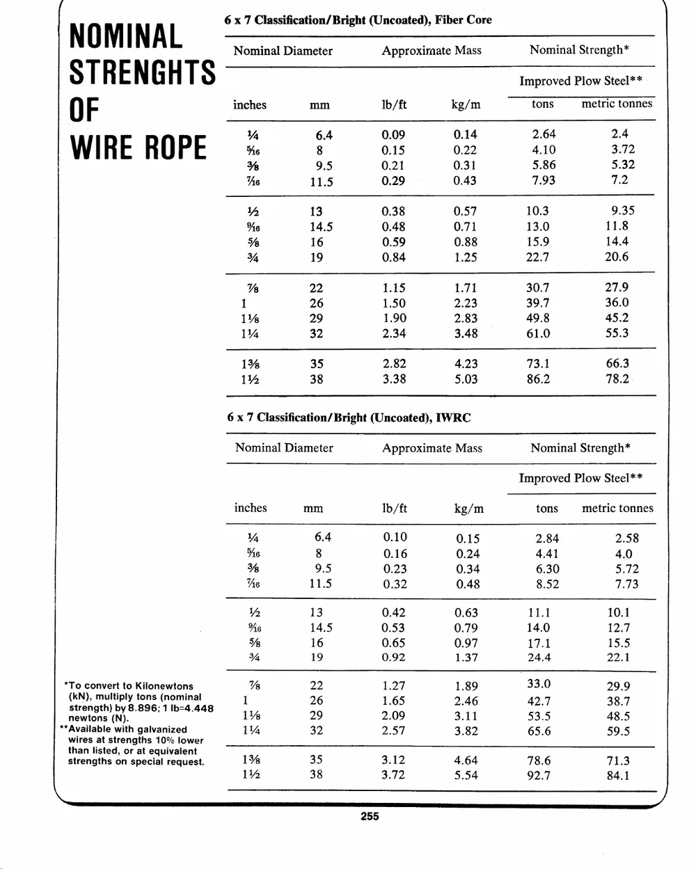
N0M NA [ 6 x 7 Classification/ Bright (Uncoated), Fiber Core
Nominal Diameter Approxirnate Mass Nominal Strength*
ST R E N G H T S inches mm lb/ft kg/m Improved Plow Steel** .
0F tons metric tonnes
WIRE ROPE A%e 86.4 00..1059 00..2124 42..6140 23..472
�% 9.5 0.21 0.31 5.86 5.32
Ae 11.5 0.29 0.43 7.93 7.2
2 13 0.38 0.57 10.3 9.35
13.0 11.8
te 14.5 0.48 0.71
15.9 14.4
% 16 0.59 0.88 22.7 20.6
Y 19 0.84 1.25
% 22 1.15 1.71 30.7 27.9
1.50 2.23 39.7 36.0
1 26 1.90 2.83 49.8 45.2
2.34 3.48 61.0 55.3
1% 29
1% 32
1% 35 2.82 4,23 73.1 66.3
3.38 5.03 86.2 78.2
1% 38
6 x 7 Classification/ Bright (Uncoated), IWRC
Nominal Diameter Approximate Mass Nominal Strength*
Improved Plow Steel**
inches mm Ib/ft kg/m tons metric tonnes
*To convert to Kilonewtons VY 6.4 0.10 0.15 2.84 2.58
(KN), multiply tons (nominal Ae 8 0.16 0.24 4.41 4.0
newtons (ND. Ss trength) by 8.896; 1 Ib=4.44
** Available with galvanized % 9.5 0.23 0.34 6.30 5.72
As 11.5 0.32 0.48 8.52 7.73
wires at strengths 10% lower
than listed, or at equivalent iY 13 0.42 0.63 11.1 10.1
%e 14.5 0.53 0.79 14.0 12.7
strengths on special request. Ys 16 0.65 0.97 17.1 15.5
% 19 0.92 1.37 24.4 22.1
\
% 22 1.27 1.89 33.0 29.9
1 26 1.65 2.46 42.7 38.7
1% 29 2.09 3., 11 53."5 48.5
11% 32 2.57 3.82 65.6 59.5
1% 35 3.12 4.64 78.6 71.3
1% 38 3.72 5.54 92.7 84.1
J
~\
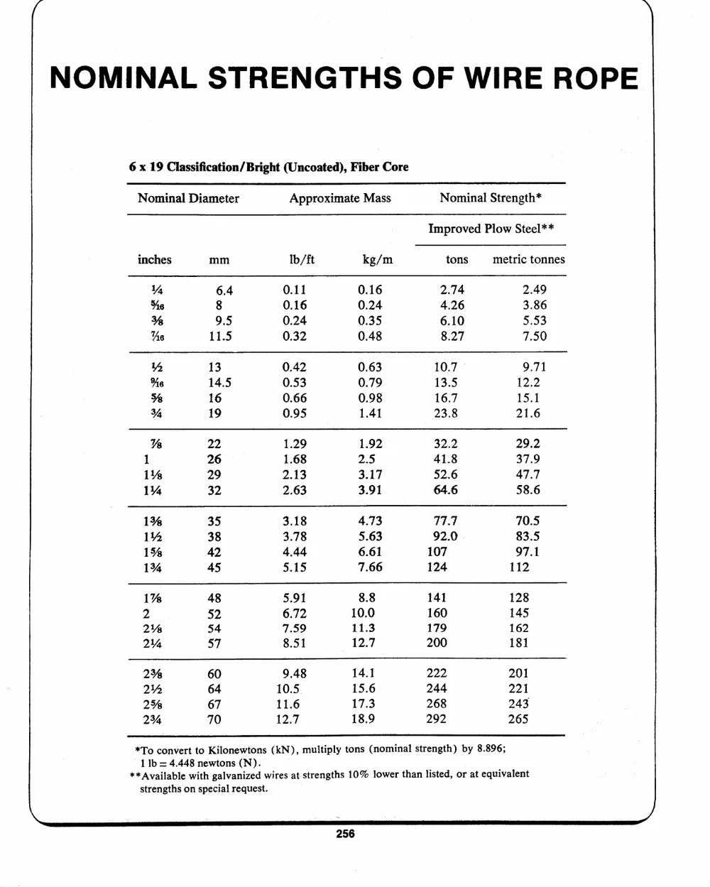
NOMINAL STRENGTHS OF WIRE ROPE
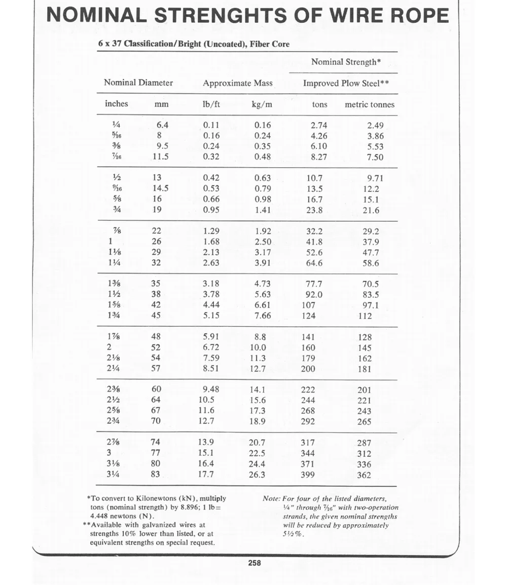
6 x 19 Classification/ Bright (Uncoated), Fiber Core
Nominal Diameter Approximate Mass Nominal Strength*
Improved Plow Steel**
inches mm lb/ft kg/m tons metric tonnes
% 6.4 0.11 0.16 2.74 2.49
0.16 0.24 4.26 3.86
%e 8
0.24 0.35 6.10 5.53
% 9.5 0.32 0.48 8.27 7.50
As 11.5
14 13 0.42 0.63 10.7 � 9.71
0.53 0.79 13.5 12.2
%e 14.5 0.66 0.98 16.7 15.1
0.95 1.41 23.8 21.6
�% 16
% 19
% 22 1.29 1.92 32.2 29.2
1 26 1.68 2.5 41.8 37.9
2.13 3.17 52.6 47.7
1% 29 2.63 3.91 64.6 58.6
1% 32
1% 35 3.18 4.73 177 70.5
3.78 5.63 92.0 83.5
1% 38 4.44 6.61 107 97.1
1% 42 5.15 7.66 124 112
1% 45
1% 48 5.91 8.8 141 128
2 52 6.72 10.0 160 145
2% 54 7.59 11.3 179 162
214 57 8.51 12.7 200 181
2% 60 9.48 14.1 222 201
214 64 10.5 15.6 244 221
2% 67 11.6 17.3 268 243
234 70 12.7 18.9 292 265
*To convert to Kilonewtons (kN), multiply tons (nominal strength) by 8.896;
1 lb = 4.448 newtons (N).
wires at strengths 10% lower than listed, or at equivalent
** Available with galvanized
strengths on special request.
~
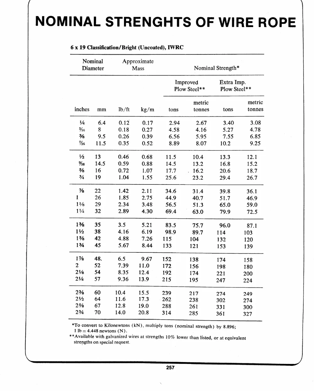
6 x 19 Classification/ Bright (Uncoated), IWRC
Nominal Approximate Nominal Strength*
Diameter Mass
Improved Extra Imp.
Plow Steel** Plow Steel**
inches mm lb/ft kg/m tons metric tons metric
tonnes tonnes
1% 6.4 0.12 0.17 2.94 2.67 3.40 3.08
6 8 0.18 0.27 4.58 4.16 5.27 4.78
0.26 0.39 6.56 5.95 7.55 6.85
�% 9.5 0.35 0.52. 8.89 8.07 10.2 9.25
Ae 11.5
WY 13 0.46 0.68 11.5 10.4 13.3 12.1
0.59 0.88 14.5 13.2 16.8 15.2
%e 14.5 0.72 1.07 17.7 . 16.2 20.6 18.7
1.04 1.55 25.6 23.2 29.4 26.7
� 16
% 19
KR 22 1.42 2.11 34.6 31.4 39.8 36.1
1.85 2.75 44.9 40.7 51.7 46.9
1 26 2.34 3.48 56.5 51.3 65.0 59.0
2.89
114% 29 4.30 69.4 -- 63.0 79.9 72.5
1% 32
1% 35 3.5 5.21 83.5 75.7 96.0 87.1
4.16 6.19 98.9 89.7 114 103
1% 38 4.88 7.26 115 104 132 120
5.67 8.44 133 121 153 139
1% 42
134 45
1% 48. 6.5 9.67 152 138 174 158
7.39 11.0 172 156 198 180
2 �2 8.35 12.4 192 174 221 200
9.36 13.9 215 195 247 224
2% 54
2% 57
2% 60 10.4 15.5 239 217 274 249
11.6 17.3 262 238 302 274
2% 64 12.8 19.0 288 261 331 300
14.0 20.8 314 285 361 327
2% 67
2% 70
*To convert to Kilonewtons (KN), multiply tons (nominal strength) by 8.896;
1 1b = 4.448 newtons (N).
** Available with galvanized wires at strengths 10% lower than listed, or at equivalent
strengths on special request.
~
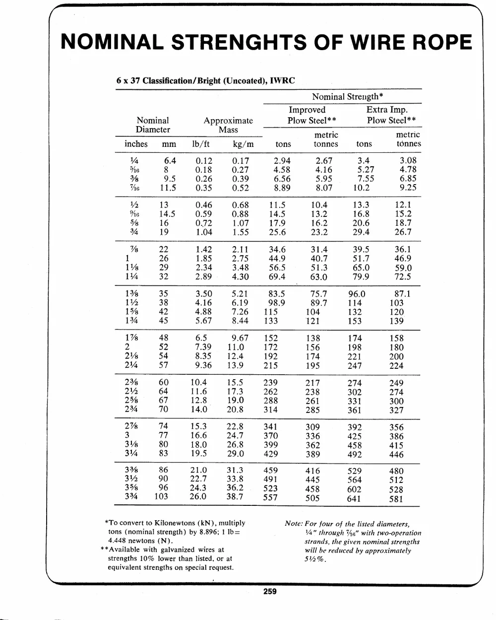
6 x 37 Classification/ Bright (Uncoated), IWRC
Nominal Strength*
Nominal Approximate Improved Extra Imp.
Diameter Mass Plow Steel** Plow Steel**
inches mm
metric metric
lb/ft kg/m tons tonnes tons tonnes
% 6.4 0.12 0.17 2.94 2.67 3.4 3.08
4.58 4.16 5.27 4.78
"6 8 0.18 0.27 6.56 5.95 7.55 6.85
�% 9.5 0.26 0.39 8.89 8.07 10.2 9.25
Ae 11.5 0.35 0.52
i) 13 0.46 0.68 11.5 10.4 13.3 12.1
6 14.5 0.59 0.88 14.5 13.2 16.8 15.2
Ye 16 0.72 1.07 17.9 16.2 20.6 18.7
4% 19 1.04 1.55 25.6 23.2 29.4 26.7
% 22 1.42 2.11 34.6 31.4 39.5 36.1
1 26 1.85 2.75 44.9 40.7 51.7 46.9
2.34 3.48 56.5 51.3 65.0 59.0
1% 29 2.89 4.30 69.4 63.0 79.9 72.5
1% 32
1% 35 3.50 �.21 83.5 75.7 96.0 87.1
4.16 6.19 98.9 89.7 114 103
1% 38
4.88 7.26 115 104 132 120
1% 42 5.67 8.44 133 121 153 139
1% 45
1% 48 6.5 9.67 152 138 174 158
7.39 11.0 172 156 198 180
2 52 8.35 12.4 192 174 221 200
9.36 13.9 215 195 247 224
2% 54
2% 57
2% 60 104 �155 239 217 274 249
214 64 11.6 17.3 262 238 302 274
2�8 67 12.8.
19.0 288 261 331 300
2% 70 14.0
20.8 314 285 361 327
2% 74 15.3 22.8 341 309 392 356
16.6 24.7 370 336 425 386
3 77 18.0 26.8 399 362 458 415
19.5 29.0 429 389 492 446
3% 80
31% 21.0 31.3 459 416 $29 480
22.7 33.8 491 445 564 512
3% 86 24.3 36.2 523 458 602 528
26.0 38. $57 505 641 581
314 90
3%
3% 96
\ *To convert to Kilonewtons (KN), multiply Note: For four of the listed diameters, )
tons (nominal strength) by 8.896; 1 lb= Y%4" through (g" with two-operation
4.448 newtons (N). strands, the given nominal strengths
will be reduced by approximately
**Available with galvanized wires at SIAM,
strengths 10% lower than listed, or at
|
| equivalent strengths on special request.
~
NOMINAL STRENGHTS OF WIRE ROPE
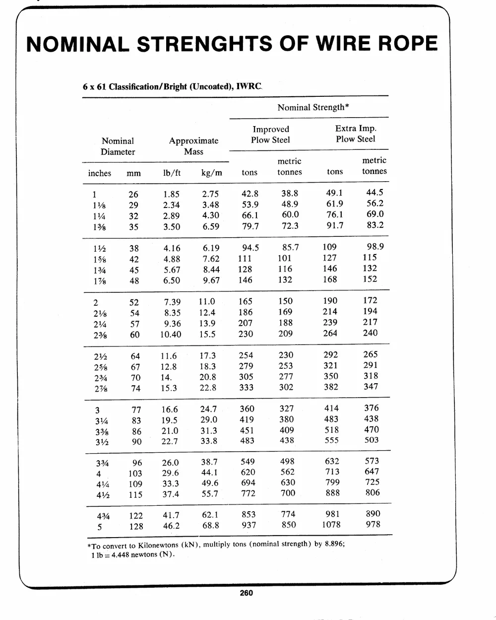
6 x 61 Classification/ Bright (Uncoated), IWRC.
Nominal Strength*
Nominal Approximate Improved Extra Imp.
Diameter Mass Plow Steel Plow Steel
inches mm metric metric
tons tonnes
lb/ft kg/m tons tonnes
1 26 1.85 2.75 42.8 38.8 49.1 44.5
53.9 48.9 61.9 56.2
1% 29 2.34 3.48 66.1 60.0 76.1 69.0
1% 32 2.89 4.30
1% 35 3.50 6.59 79.7 72.3 91.7 83.2
1% 38 4.16 6.19 94.5 85.7 109 98.9
7.62 111 101 127 115
15% 42 4.88 8.44 128 116 146 132
1% 45 5.67 152
1% 48 6.50 9.67 146 132 168
2 52 7.39 11.0 165 150 190 172
186 169 214 194
2% 54 8.35 12.4 207 188 239 217
2% 57 9.36 13.9
2% 60 10.40 15.5 230 209 264 240
2142 64 11.6 17.3 254 230 292 265
18.3 279 253 321 291
2% 67 12.8 20.8 305 277 350 318
2% 70 14.
2% 74 15.3 22.8 333 302 382 347
3 77 16.6 24.7 | 360 327 414 376
29.0 419 380 483 438
31% 83 19.5 31.3 451 409 518 470
3% 86 21.0 438
314 90 22.7 33.8 483 555 503
3% 96 26.0 38.7 549 498 632 573
44.1 620 562 713 647
4 103 29.6 694 630 799 725
4% 109 33.3 49.6
44 115 37.4 55.7 772 700 888 806
43% 122 41.7 62.1 853 774 981 890
5 128 46.2 68.8 937 850 1078 978
*To convert to Kilonewtons (kN), multiply tons (nominal strength) by 8.896;
1 Ib = 4.448 newtons (N).
~
NOMINAL STRENGTHS OF WIRE ROPE |
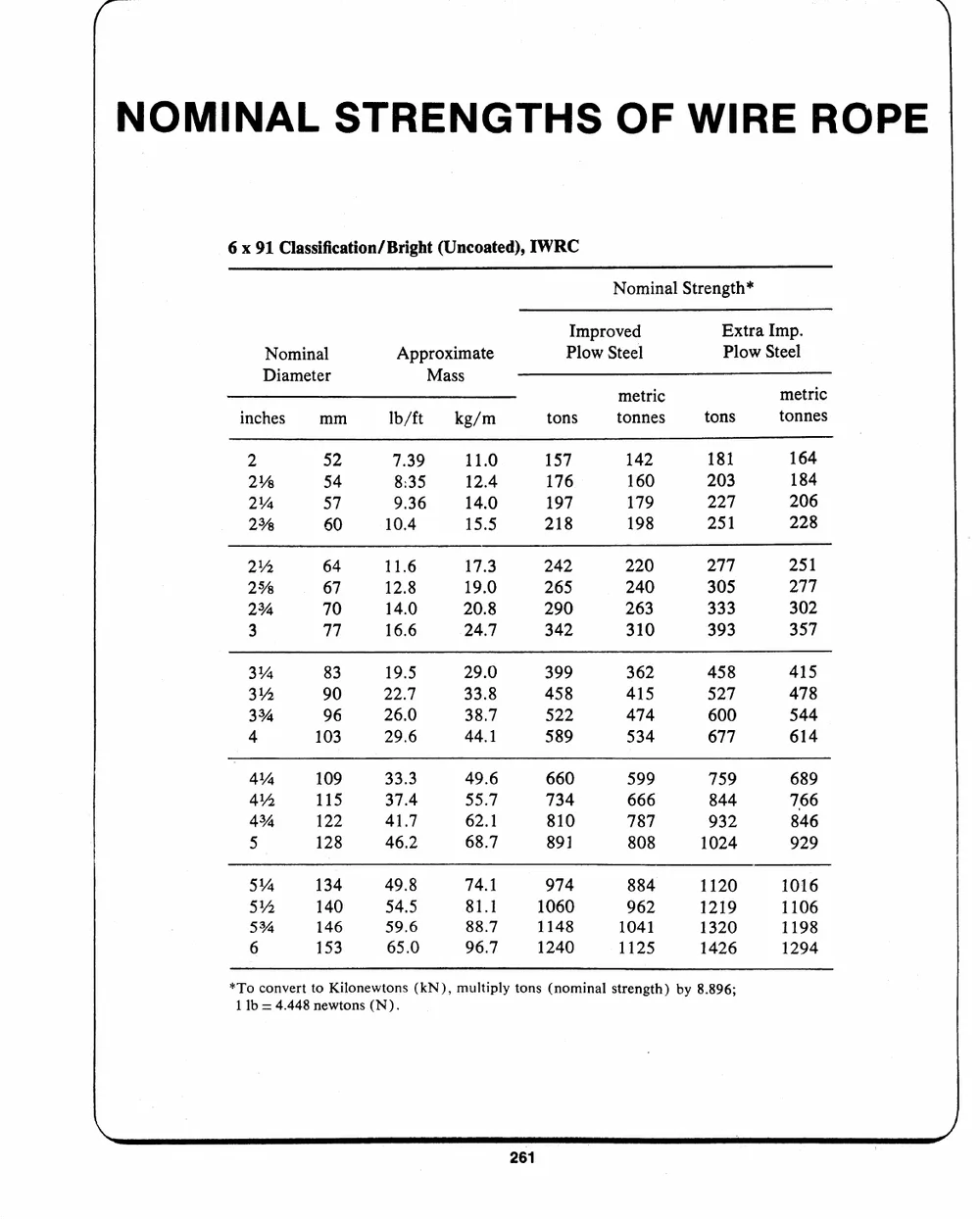
6 x 91 Classification/ Bright (Uncoated), IWRC
Nominal Strength*
Nominal Approximate Improved Extra Imp.
Diameter Mass Plow Steel Plow Steel
Ib/ft kg/m metric tons metric
tons tonnes tonnes
inches mm
2 52 7.39 11.0 157 142 181 164
2% 54 8:35 12.4 176 160 203 184
2% 57 9.36 14.0 197 179 227 206
2% 60 10.4 15.5 218 198 251 228
2" 64 11.6 17.3 242 220 277 251
2% 67 12.8 19.0 265 240 305 277
2% 70 14.0 20.8 290 263 333 302
3 77 16.6 24.7 342 310 393 357
3% 83 19.5 29.0 399 362 458 415
3% 90 22.7 33.8 458 415 527 478
3% 96 26.0 38.7 522 474 600 544
4 103 29.6 44.1 589 534 677 614
4% 109 33.3 49.6 660 599 759 689
414 115 37.4 55.7 734 666 844 766
43% 122 41.7 62.1 810 787 932 846
5 128 46.2 68.7 891 808 1024 929
5% 134 49.8 74.1 974 884 1120 1016
81.1 1060 962 1219 1106
5Y% 140 54.5 88.7 1148 1041 1320 1198
96.7 1240 1125 1426 1294
5% 146 59.6
6 153 65.0
*To convert to Kilonewtons (kN), multiply tons (nominal strength) by 8.896;
1 Ib = 4.448 newtons (N).
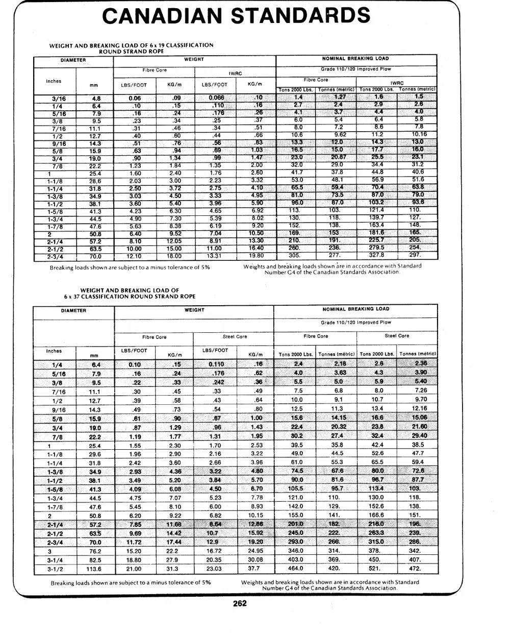
CANADIAN STANDARDS
WEIGHT AND BREAKING LOAD OF 6x 19 CLASSIFICATION
ROUND STRAND ROPE
NOMINAL BREAKING LOAD
DIAMETER WEIGHT
Inches LBS/FOOT KG/m IWRC
LBS/FOOT
3/16
= : 1
Breaking loads shown are subject to a minus tolerance of 5% Weights and breaking loads shown are in accordance with Standard
Number G4 of the Canadian Standards Association.
WEIGHT AND BREAKING LOAD OF
6 x 37 CLASSIFICATION ROUND STRAND ROPE
DIAMETER WEIGHT NOMINAL BREAKING LOAD
Grade 110/120 Improved Plow
Fibre Core Steel Core Fibre Core Steet Core
LBS/FOOT LBS/FOOT Tons 2000 Lbs. | Tonnes (m�tric) | Tons 2000 Lbs. | Tonnes (m�tric)
2-1
2-3/4
3 76.2 15.20 22.2 16.72 24.95 346.0 314. 378. 342.
3-1/4 82.5 18.80 27.9 20.35 30.08 403.0 369. 450. 407.
3-1/2 113.6 21.00 31.3 23.03 37.7 464.0 420. 521. 472.
\ Breaking loads shown are subject to a minus tolerance of 5% WeightsNaunmdbberreaGk4inogf ltohaedCsasnhaodwinanarSetainndaacrcdosrdAsasnocceiawtiitohn.Standard
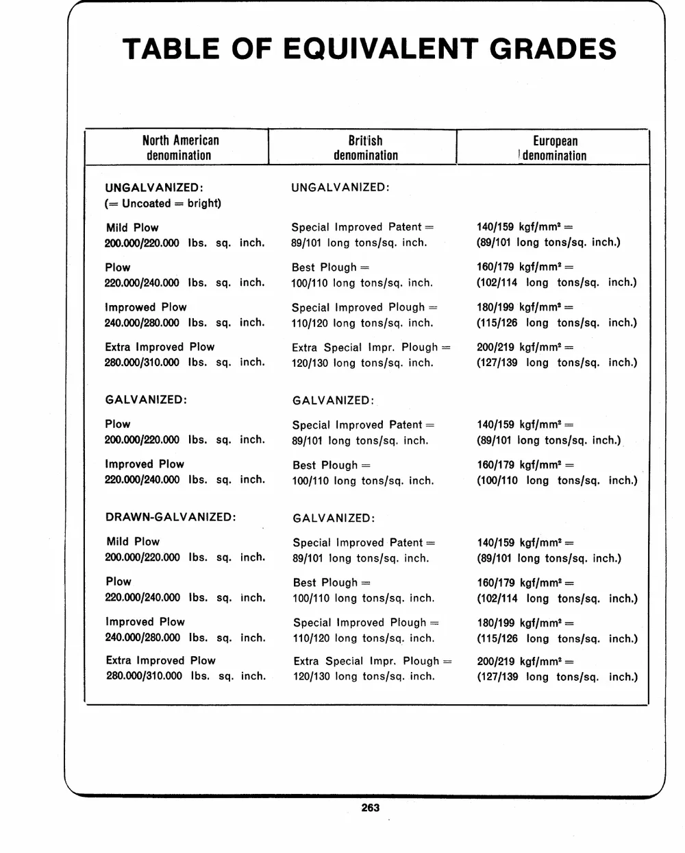
TABLE OF EQUIVALENT GRADES
North American British European
denomination denomination | denomination
UNGALVANIZED: UNGALVANIZED: 140/159 kgf/mm? =
(= Uncoated = bright) (89/101 long tons/sq. inch.)
Special Improved Paten=t 160/179 kgf/mm? =
Mild Plow 89/101 long tons/sq. inch. (102/114 long tons/sq. inch.)
200.000/220.000 Ibs. sq. inch. 180/199 kgf/mm=?
Best Plough = (115/126 long tons/sq. inch.)
Plow 100/110 long tons/sq. inch. 200/219 kgf/mm=?
220.000/240.000 Ibs. sq. inch. Special Improved Plough = (127/139 long tons/sq. inch.)
110/120 long tons/sq. inch.
Improwed Plow Extra Special Impr. Ploug=h
240.000/280.000 Ibs. sq. inch. 120/130 long tons/sq. inch.
Extra Improved Plow
280.000/310.000 Ibs. sq. inch.
GALVANIZED: GALVANIZED: 140/159 kgf/mm? =
(89/101 long tons/sq. inch.)
Plow Special Improved Paten=t
200.000/220.000 Ibs. sq. inch. 89/101 long tons/sq. inch. 160/179 kgf/mm? = .
Improved Plow Best Plough = (100/110 long tons/sq. inch.)
220.000/240.000 Ibs. sq. inch. 100/110 long tons/sq. inch.
DRAWN-GALVANIZED: GALVANIZED: 140/159 kgf/mm? =
(89/101 long tons/sq. inch.)
Mild Plow Special Improved Patent =
200.000/220.000 Ibs. sq. inch. 89/101 long tons/sq. inch. 160/179 kgf/mm? =
(102/114 long tons/sq. inch.)
Plow Best Plough =
220.000/240.000 Ibs. sq. inch, 100/110 long tons/sq. inch. 180/199 kgf/mm? =
(115/126 long tons/sq. inch.)
Improved Plow Special Improved Plough =
240.000/280.000 Ibs. sq. inch. 110/120 long tons/sq. inch. 200/219 kgf/mm=?
(127/139 long tons/sq. inch.)
Extra Improved Plow Extra Special Impr. Ploug= h
280.000/310.000 Ibs. sq. inch. 120/130 long tons/sq. inch.
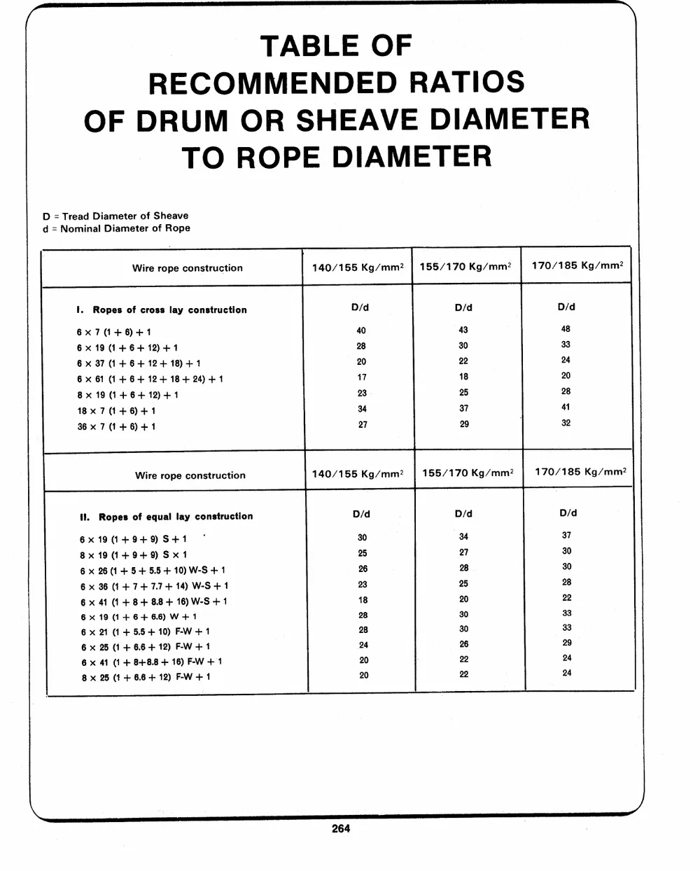
TABLE OF
RECOMMENDED RATIOS
OF DRUM OR SHEAVE DIAMETER
TO ROPE DIAMETER
D = Tread Diameter of Sheave 140/155 Kg/mm?2| 155/170 Kg/mm?2 170/185 Kg/mm?
d = Nominal Diameter of Rope
D/d D/d D/d
Wire rope construction
40 43 48
i. Ropes of cross lay construction
6x7(1+6)+1 28 30 33
6x 19 (1+6+ 12) +1
6 x 37 (1+6+ 12+ 18) +1 20 22 24
6 x 61 (1+ 6+ 12+ 18+24) +1
8x 19 (1 +6+ 12)+1 17 18 20
18x 7(1+6)+1
23 . 25 28
36x 7 (1+6) +1
34 37 41
Wire rope construction . 32
27 29
ll. Ropes of equal lay construction
6x19(1+9+9) S+1 , 140/155 Kg/mm2 155/170 Kg/mm2 170/185 Kg/mm2
8x191+9+9)Sx1
6 x 26 (1+ 5+5.5 + 10) W-S + 1 D/d ; D/d D/d
6x 36 (1+ 7+ 7.7 + 14) W-S + 1
6 x 41 (1+ 8+ 88+ 16) W-S + 1 30 34 37
6x19 (1+6+ 66) W+ 1 25 27 30
6 x 21 (1+ 5.5 + 10) F-W+1 28 |
6 x 25 (1 + 6.6 + 12) F-W +1 26 25 28
6 x 41 (1 + 8+8.8 + 16) F-W +1 23
18 20 22
8 x 25 (1+ 6.6 + 12) F-W +1
28 30 33
28 30 29
24 22 24
20 22 24
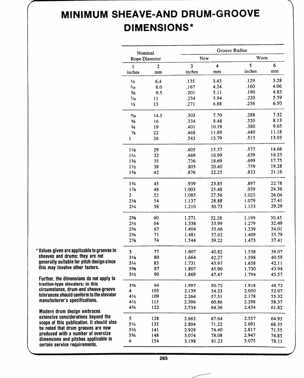
MINIMUM SHEAVE-AND DRUM-GROOVE
DIMENSIONS*
Nominal Groove Radius
Rope Diameter New Worn
1 2 4 5 6
inches mm inches mm
inches mm 135
.167
VY 6.4 .201 3.43 .129 3.28
.234 4.24 .160 4.06
he 8.0 271 5.11 .190 4.83
% 9.5
As 11 5.94 .220 5.59
6.88 .256 6.50
~ 13
%e 14.5 303 7.70 .288 7.32
8.48 .320 8.13
Ye 16 334 10.19 .380 9.65
Ye 19 401
22 468 11.89 .440 11.18
% 513 13.03
1 26 543 13.79
1% 29 .605 15.37 577 14.66
16.23
1% 32 669 16.99 .639
1% 35 .736 18.69 .699 17.75
1% 38 .803 20.40 .759 19.28
1% 42 876 22.25 833 21.16
1% 45 .939 23.85 897 22.78
1% 48 1.003 25.48 959 24.36
2 52
2% 54 1.085 27.56 1.025 26.04
2% 58 1.137 28.88 1.079 27.41
1.210 30.73 1.153 29.29
2% 60 1.271 32.28 1.199 30.45
2% 64 1.338 33.99 1.279 32.49
2% 67 1.404 35.66 1.339 34.01
23% 71 1.481 37.62 1.409 35.79
2% 74 1.544 39.22 1.473 37.41
*Values given are applicable to grooves in 3 77 1.607 40.82 1.538 39.07
sheaves and drums; they are not 3% 80 1.664 42.27 1.598 40.59
34 83
generally suitable for pitch design since 35% 87 1.731 43.97 1.658 42.11
this may involve other factors. 1.807 45.90 1.730 43.94
Further, the o, do not apply to 3% 90 1.869 47.47 1.794 45.57
dimensions 1.997 50.72 1.918 48.72
tcriarcctuimosnt-atnycpee,eldervuamto-rasn;disn htehaivse-groove 334 96
4 103 2.139 54.33 2.050 52.07
tmoalneurfaanccteusrserh'osulsdpeccoinffiocartmitoonst.he elevator 4 109
44 115 2264 57.51 4178 55.32
Modern drum desi, gn embraces 4% 122 2.396 60.86 7.298 58.37
sexctoepnesiovfethci�osnspiudbelir�caoatttitioonns. bIteysohnoudltdhealso
a5 y 113258 2.534 64.36 2.434 61.82
be noted that drum grooves are now 5 141 a-
534 148 >2.860643 7671..6242 72.659517
pdirmoednuscieodnwsitahnda pniutcmhbeesrapofploivcearbsliezeto 6 154 7155
2.929 74.40 2817
certain service requirements. 74 85
3.07 4 78.08 49 47 78 it
3.198 81.23 3.075
, , `
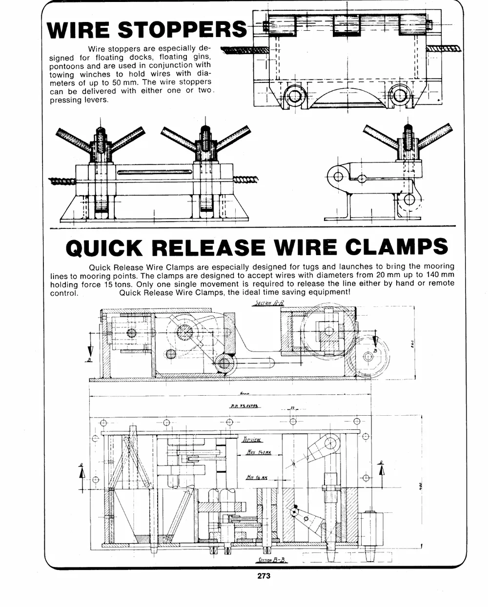
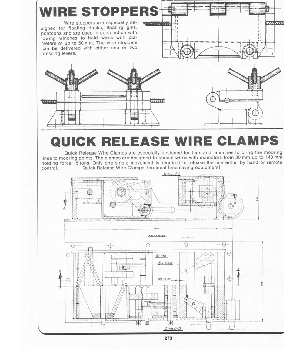
WIRE STOPPERS
Wire stoppers are especially de-
wee
stpioogwnnitenodgonsfwoiranncfdhleoasarteitnuogsehddoolcidknsc,woinrfjelusonactwtiinitgohn gins,
with
dia-
meters of up to 50 mm. The wire stoppers
can be delivered with either one or two,
pressing levers.
QUICK RELEASE WIRE CLAMPS
Quick pRtoeoinlnset.sa.sOeTnlhWyeircoelnaeCmlpsaismnpgalsreeadmreeosveiesgpmneeecnditatloliysacdrceeeqspuiitgrnweedidrtefosorrweitltuehgassdeiaantmdheetlelariusnnecfehrieotsmhet2ro0bbmyrmihnagunptdhteoorm1or4oe0rmimontmge
lines to mooring Quick Release Wire Clamps, the ideal time saving equipment!
holding force 15
control.
wECTION LL et
aa ate
hea ee A ey
PR VS V6vsh
we W.J. KEATING LIMITED
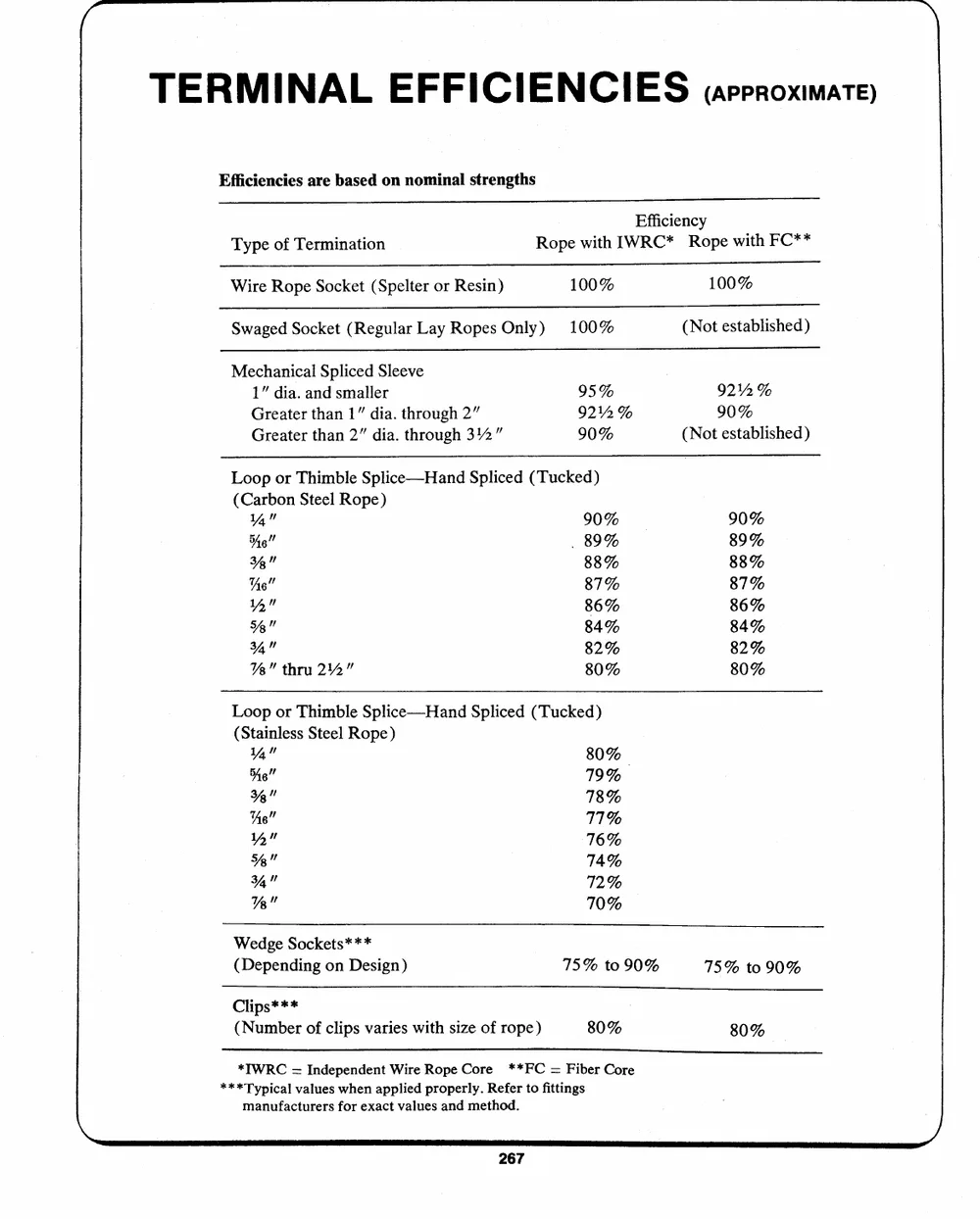
TERMINAL EFFICIENCIES (approximate)
Efficiencies are based on nominal strengths
Type of Termination Efficiency
Rope with IWRC* Rope with FC**
Wire Rope Socket (Spelter or Resin) 100% 100%
Swaged Socket (Regular Lay Ropes Only) 100% (Not established)
Mechanical Spliced Sleeve 95% 921%. %
9212 % 90%
1" dia. and smaller 90% (Not established)
Greater than 1" dia. through 2"
Greater than 2" dia. through 312"
Loop or Thimble Splice--Hand Spliced (Tucked)
(Carbon Steel Rope)
4" 90% 90%
89%
oe" . 89% 88%
87%
Ya" 88% 86%
84%
Ae" 87% 82%
80%
1A" 86%
Ye" 84%
34" 82%
%" thru 2142" 80%
Loop or Thimble Splice---Hand Spliced (Tucked)
(Stainless Steel Rope)
Ya" 80%
He" 79%
�" 78%
Ae" 711%
Yn" 76%
�e" 74%
wm" 12%
Ya" 70%
Wedge Sockets*** 75% to 90% 75% to 90%
(Depending on Design)
Clips*** 80% 80%
(Number of clips varies with size of rope)
*ITWRC = Independent Wire Rope Core **FC = Fiber Core
***Typical values when applied properly. Refer to fittings
manufacturers for exact values and method.
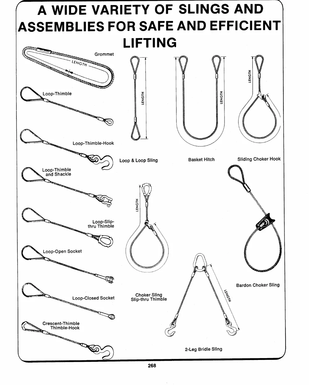
(A WIDE VARIETY OF SLINGS AND *
ASSEMBLIES FOR SAFE AND EFFICIENT
LIFTING
LENGTH
LENGTH
Loop & Loop Sling Basket Hitch
Loop-Thimble
and Shackle
hs,
y
Loop-Slip-
thru Thimble
( N,Le07-onen Socket
re,
Choker Sling
Slip-thru Thimble
L Crescent-Thimble
Thimble-Hook
2-Leg Bridle Sling
x DS"
,
ae
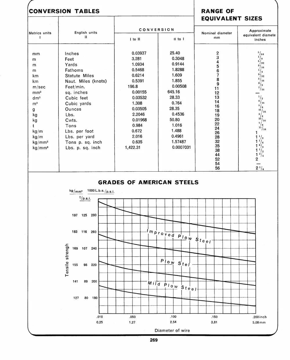
CONVERSION TABLES RANGE OF
EQUIVALENT SIZES
MetricsI units EnglishHl units CONVERSION Nominalmmdiameter equiAvpaplrenotxidmiaatmeete
inches
I to fl Hl to |
mm Inches 0.03937 25.40 2 5/64
35 ails
mm YFaeredt s 31..2089134 00..93104448 6 vi
m Fathoms 0.5468 1.8288 87 P9/i5e0
00..56329114 11..865059 � ff
km Statute Miles 42 --
196.8 0.00508 13 Ly
kmm/sec NFaeuett/.miMn.iles (knots) 1i4 aAhfs
0.00155 645.16 19 3),
mm? sq. inches 20 13/44
0.03532 28.33 2`2 , ifsos
dm? Cubic feet 28 1/5
01..30038505 280..37564
gm> OCuubniccesyards 0.4536 32 14/4
2.2046 3 1
kg Lbs. 50.80 44 19),
0.01968
kg Cwts. 11..408186
00..697824
tkg/m LTbosn.s per foot 0.4961
2.016 1.57487
kg/m Lbs. per yard
kg/mm? Tons p. sq. inch 0.635 0.0007031
kg/mm? Lbs. p. sq. inch 1,422.31
52 2
54 --
56 21),
GRADES OF AMERICAN STEELS
kg/mm? 1000L.b.s./p 5.1.
t/p.s.i.
197 125 280
183 116 260
Tensile strengh 169 107 240
155 98 220
144 89 200
127 80 180
.010 .050 100 150 .200inch
0,25 1,27 2,54 3,81 5,08 mm
Diameter of wire y,
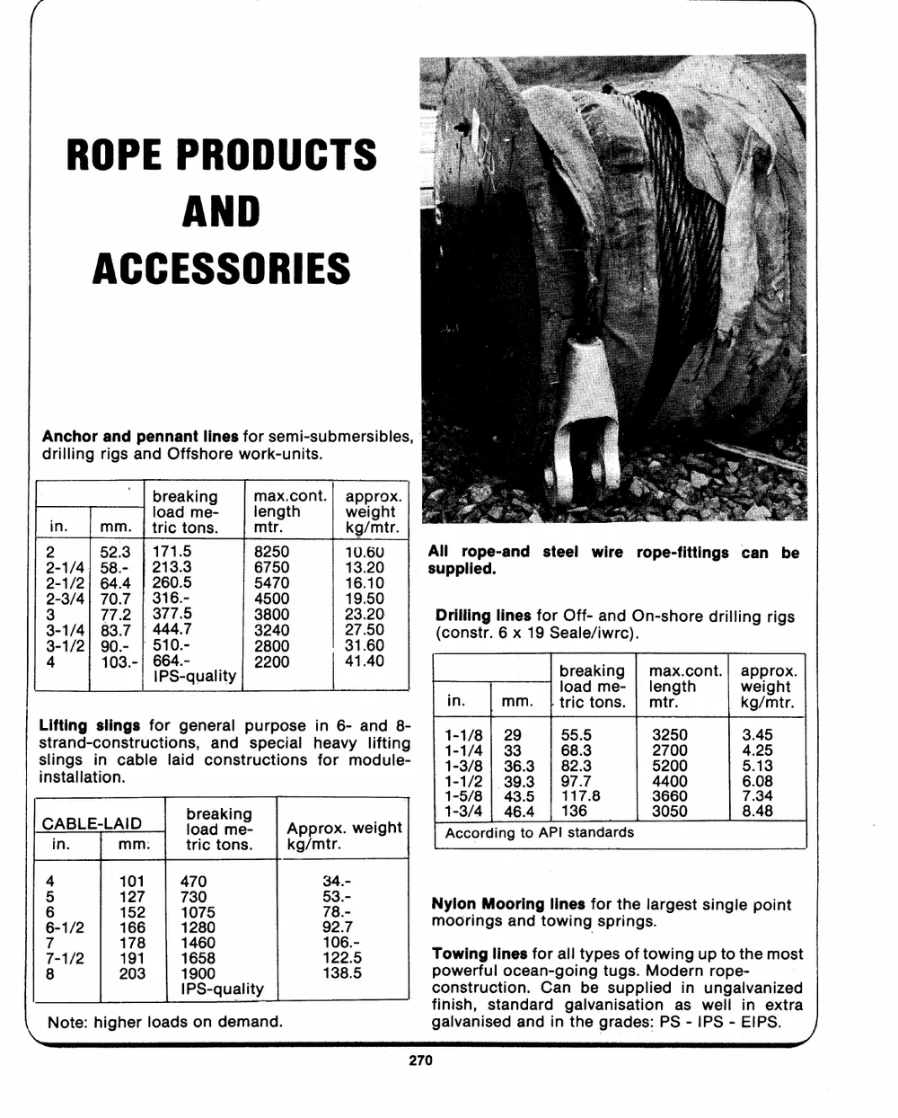
ROPE PRODUCTS
AND
ACCESSORIES
Anchor and pennant lines for semi-submersibles,
drilling rigs and Offshore work-units.
' | breaking max.cont.| approx.
load me-
in. mm. | tric tons. length weight
mtr. kg/mtr.
2 52.3 el 8 All rope-and steel wire rope-fittings can be
2-1/4| 58.- | 6250 10.60
2-1/2} 64.4 . supplied.
2-3/4| 70.7 | 260.5 5470 13. Drilling lines for Off- and On-shore drilling rigs
3 77.2 | 316.- 4500 16.10
3-1/4) 83.7 | 377.5 3800 19.50 (constr. 6 x 19 Seale/iwrc).
23.20
| AO, 3240
aes
4 108.- PS.quality 2200 41.40 breaking | max.cont.| approx.
--_---- load me- | length weight
In. mm. }|tric tons. | mtr. kg/mtr.
sLitfrtainndg-csolnisntgrsucftoirongse,neraanld psuprepcioasle hinea6v-y alnidfti8n-g We re 23 3200 oe
1-3/8 | 36.3 | 823 5200 5.13
slings in cable laid constructions for module-
1-1/2 | 39.3 | 97.7 4400 6.08
installation. 1-5/8 | 43.5 117.8 3660 7.34
breaking 1-3/4 | 46.4 | 136 3050 8.48
CABLE LAID Approx. weight According to API standards
in. mm: load me-
kg/mtr.
tric tons.
4 101 470 34.- Nylon Mooring lines for the largest single point
25 ie
2 166 1280 23." moorings and towing springs.
6-1/2 92.7 Towing lines forall types of towing up to the most
4/2 190 \ecp 112026..5- powerful ocean-going tugs. Modern rope-
8 203 1900 construction. Can be supplied in ungalvanized
138.5 finish, standard galvanisation as well in extra
IPS-quality galvanised and in the grades: PS - IPS - EIPS. /
--
\_Note: higher loads on demand.
\
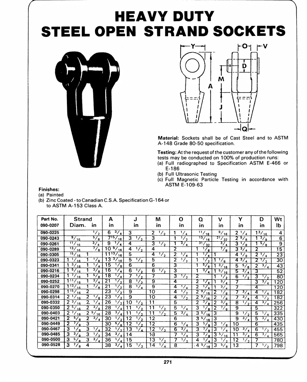
HEAVY DUTY
STEEL OPEN STRAND SOCKETS
po - fO~ Fv
}
Material: Sockets shall be of Cast Steel and to ASTM
A-148 Grade 80-50 specification.
Testing: At the request of the customer anyofthe following
tests may be conducted on 100% of production runs:
(a) Full radiographed to Specification ASTM E-466 or
E-186
(b) Full Ultrasonic Testing
(c) Full Magnetic Particle Testing in accordance with
Finishes: ASTM E-109-63
(a) Painted
(b) Zinc Coated - to Canadian C.S.A. Specification G-164 or
to ASTM A-153 Class A.
Part No. Strand A
090-0207 Diam. in in
090-0305
090-0323
090-0341
090-0216
090-0234
090-0252
090-0270
090-0298
090-0314
090-0332
090-0403
090-0421
090-0467
090-0485
090-0528
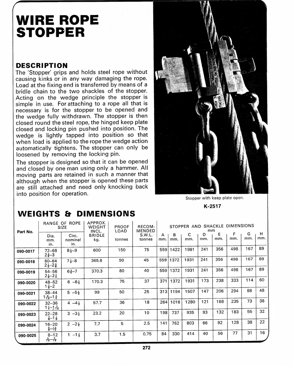
WIRE ROPE
STOPPER
DESCRIPTION Stopper with keep plate open.
The `Stopper' grips and holds steel rope without K-2517
causing kinks or in any way damaging the rope.
Load at the fixing end is transferred by means of a
bridle chain to the two shackles of the stopper.
Acting on the wedge principle the stopper is
simple in use. For attaching to a rope all that is
necessary is for the stopper to be opened and
the wedge fully withdrawn. The stopper is then
`closed round the steel rope, the hinged keep plate
closed and locking pin pushed into position. The
wedge is lightly tapped into position so that
when load is applied to the rope the wedge action
automatically tightens. The stopper can only be
loosened by removing the locking pin.
The stopper is designed so that it can be opened
and closed by one man using only a hammer. All
moving parts are retained in such a manner that
although when the stopper is opened these parts
are still attached and need only knocking back
into position for operation.
RANGESIOZFE ROPE| AWPEPIRGOHXT. PROOF RECOM- STOPPER AND SHACKLE DIMENSIONS
Part No. BIRNICDLL. E MtESo.NnWDn.eLEs.D jj mmD.m|mmmE.
Dia. Circ. LOAD A B | mCmc . | mmF. | G H
090-0017 kg. `tonnes
mm. nominal |mm.! mm. mm. | mm.
090-0018 150
in. in. 600 75 55911422} 1981 | 241 356 498 167 | 89
090-0019 72-68 84-9 90
090-0020 23-3
090-0021 60-64 74-8 365.8 80 45 559/1372 | 1931 | 241 356 498 167 | 89
090-0022 75
090-0023 24-22 370.3 50 40 559|1372| 1931 | 241 356 498 167 | 89
090-0024 54-56 63-7 36
\0900025 24-2� 20
48-52 6 -64 170.3 5 37 371}1372| 1931 | 173 238 333 114 | 60
13$-2 1.5
38-44 5 -5s 99 25 313|1194| 1507 | 147 206 294 88 48
1352--1326
4 -44 57.7 18 26411016} 1280 | 121 168 235 73 38
T22i-t28e 3 -34
z4t 23.2 10 198] 737 935 93 132 183 55 32
168-208 2 -24 77 2.5 141] 762 803 66 92 128 38 22
5_13
@8---T1e2 0.75 84 | 330 414 40 56 77 31 16
5 Z 1-14 3.7 _
16 16
~
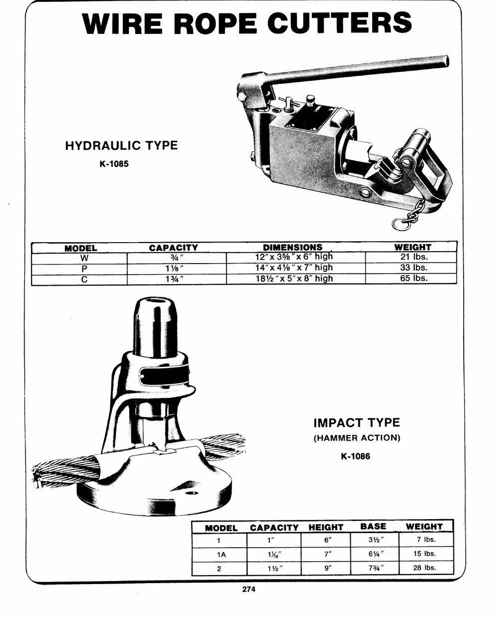
WIRE ROPE CUTTERS
HYDRAULIC TYPE
K-1085
APACITY Xx x g
% "uw "x "xX g
high
1%" 8%2"x 5"x 8"
134,"
IMPACT TYPE
(HAMMER ACTION)
K-1086
MODEL CAPACITY HEIGHT BASE WEIGHT
1 1" 6" 3%" 7 Ibs.
1A 16" 7" 6%" 15 Ibs.
2 1%" 9" 7%" 28 Ibs. /
735 AVOCA AVENUE, DORVAL, QUE., CANADA, H9P 1G4_ TEL. 514-631-9815
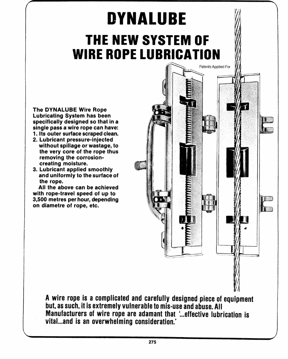
DYNALUBE
THE NEW SYSTEM OF
WIRE ROPE LUBRICATION
Patents Applied For
The DYNALUBE Wire Rope
Lubricating System has been
specifically designed so thatina
single pass a wire rope can have:
1. Its outer surface scraped clean.
2. Lubricant pressure-injected
without spillage or wastage, to
the very core of the rope thus
removing the corrosion-
creating moisture.
3. Lubricant applied smoothly
and uniformly to the surface of
the rope.
All the above can be achieved
with rope-travel speed of up to
3,500 metres per hour, depending
on diametre of rope, etc.
A wire rope is a complicated and carefully designed piece of equipment
but, as such, itis extremely vulnerable to mis-use and abuse. All
Manufacturers of wire rope are adamant that `..effective lubrication is
vital...and is an overwhelming consideration.'
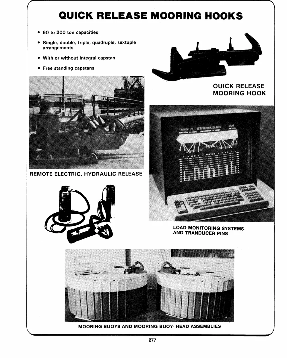
QUICK RELEASE MOORING HOOKS
60 to 200 ton capacities
Single, double, triple, quadruple, sextuple
arrangements
With or without integral capstan
Free standing capstans
QUICK RELEASE
MOORING HOOK
REMOTE ELECTRIC, HYDRAULIC RELEASE
LOAD MONITORING SYSTEMS
AND TRANDUCER PINS
\ MOORING BUOYS AND MOORING BUOY: HEAD ASSEMBLIES >,
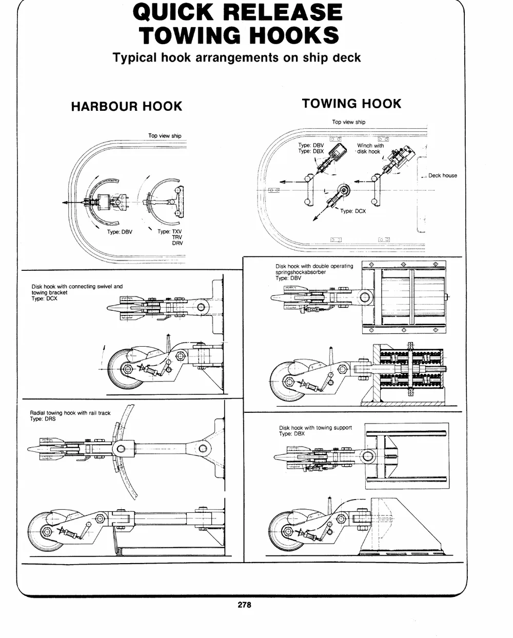
QUICK RELEASE
TOWING HOOKS
Typical hook arrangements on ship deck
HARBOUR HOOK TOWING HOOK
Top view ship Top view ship
O85 af
Winch with
`disk hook 4
i
foot Deck house
Disk hook with double operating
springshockabsorber
Type: DBV
Disk hook with connecting swivel and
towing bracket
Type: DCX iH a Uns C ee ag S epeotoe;
pep
--
Radial towing hook with rail track
Type: DRS
Disk hook with towing support
Type: DBX
_ocep ga Crm + '+
SSS tr [eer a
per ne lieee
_-- ----Cy wl tober\ d}
a--lia mi n s T)
=a an 7 : t
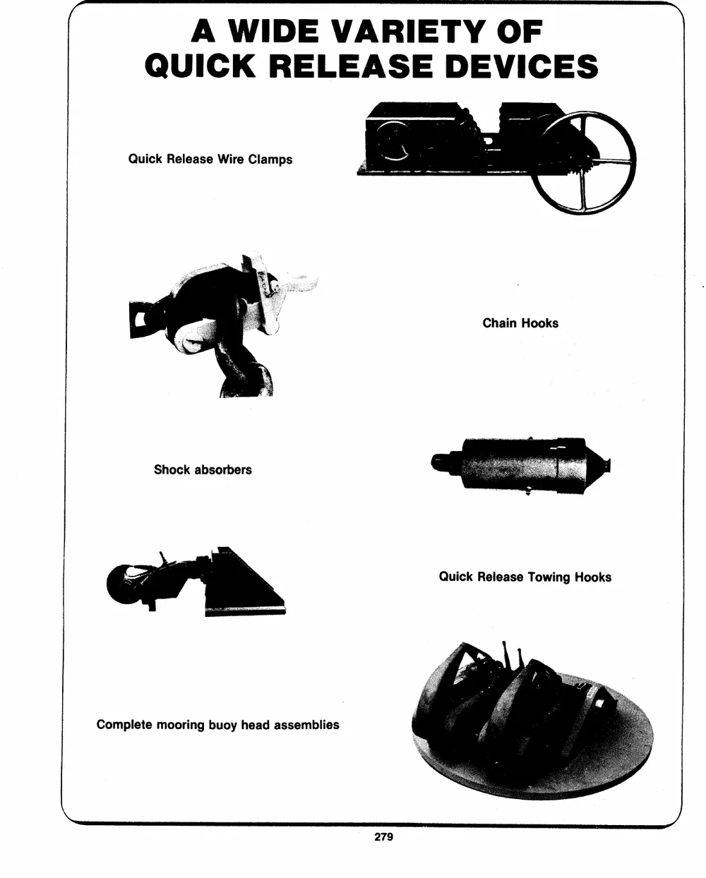
A WIDE VARIETY OF
QUICK RELEASE DEVICES
Quick Release Wire Clamps
Chain Hooks
Shock absorbers
Quick Release Towing Hooks
Complete mooring buoy head assemblies
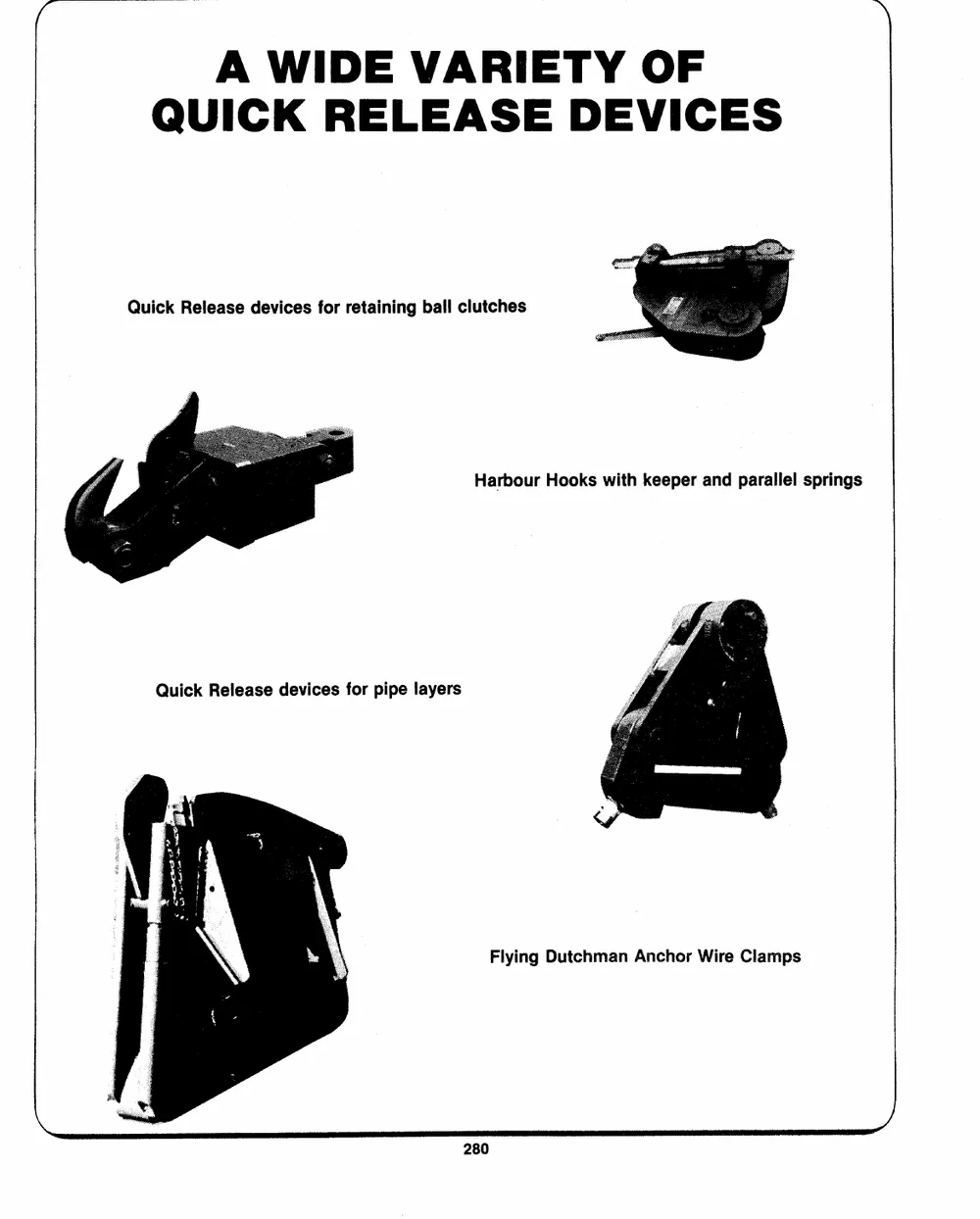
A WIDE VARIETY OF
QUICK RELEASE DEVICES
Quick Release devices for retaining ball clutches
Harbour Hooks with keeper and parallel springs
Quick Release devices for pipe layers
Flying Dutchman Anchor Wire Clamps
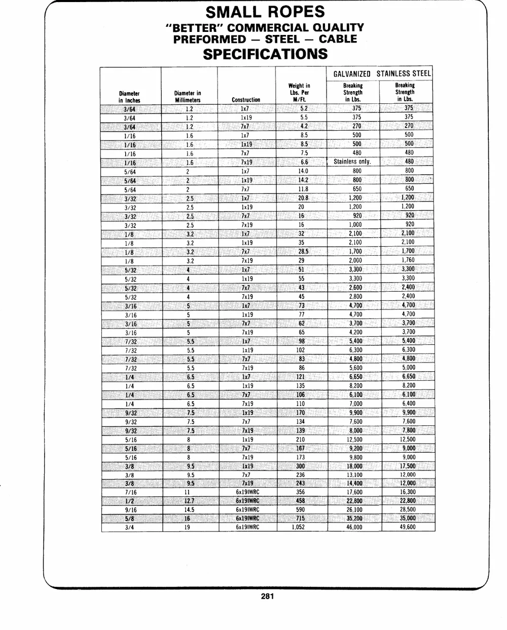
SMALL ROPES
"BETTER" COMMERCIAL QUALITY
PREFORMED -- STEEL -- CABLE
SPECIFICATIONS
Diameter Diameter in Construction Weight in GALVANIZED STAINLESS STEEL
in inches Millimeters Lbs. Per
Breaking Breaking
3/64 M/Ft. Strength Strength
1/16 in Lbs. in Lbs,
1/16
5/64 12 1x19 5.5 375 375
5/64
3/32 16 lx? 8.5 500 500
3/32
1/8 7x7 75 480 480
1/8
Stainless only.
lx? 14.0 800 800
7x] 11.8 650 650
20 1,200
16 1,000
35 2,100
29 2,000
55 3,300
45 2,800
77. 4,700
65 4,200
102 6,300
86 9,600
135 8,200
110 7,000
134 7,600
210 12,500
173 9,800
7x7 236 13,100
6x1 91WRC 17,600
6x1 91WRC 26,100
6x1 9IWRC 46,000
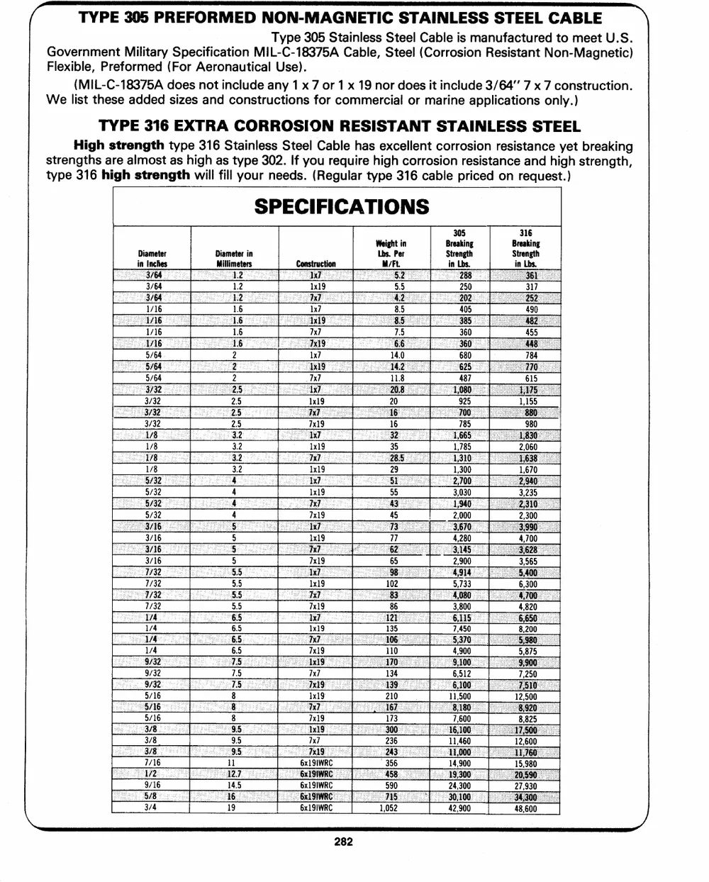
(-- TYPE 305 PREFORMED NON-MAGNETIC STAINLESS STEEL CABLE \
Type 305 Stainless Steel Cable is manufactured to meet U.S.
Government Military Specification MIL-C-18375A Cable, Steel (Corrosion Resistant Non-Magnetic)
Flexible, Preformed (For Aeronautical Use).
(MIL-C-18375A does not include any 1 x 7 or 1 x 19 nor does it include 3/64" 7 x 7 construction.
We list these added sizes and constructions for commercial or marine applications only.)
TYPE 316 EXTRA CORROSION RESISTANT STAINLESS STEEL
High strength type 316 Stainless Steel Cable has excellent corrosion resistance yet breaking
strengths are almost as high as type 302. If you require high corrosion resistance and high strength,
type 316 high strength will fill your needs. (Regular type 316 cable priced on request.)
SPECIFICATIONS
Diameter Diameter in Construction Weight in Breaking Breaking
in Inches Millimeters 1x19 Lbs. Per Strength Strength
1x7 in Lbs.
3/64 1.2 7x7 M/Ft. in Lbs.
1/16 1.6 1x7 5.5 250 317
1/16 1.6 85 490
5/64. 2 Tx] 75 405 455
5/64 2 14.0 784
3/32 25 x] 11.8 360 615
3/32 2.5 6x1 9IWRC 20
1/8 3.2 6x1 9IWRC 16 680
1/8 3.2 6x1 91WRC 35 487
29 925
4 785
5 45
5 77
5.5
5.5 102
6.5 86
6.5 135
8 134
8 210
9.5 173
ll 236
14.5 356
19 990
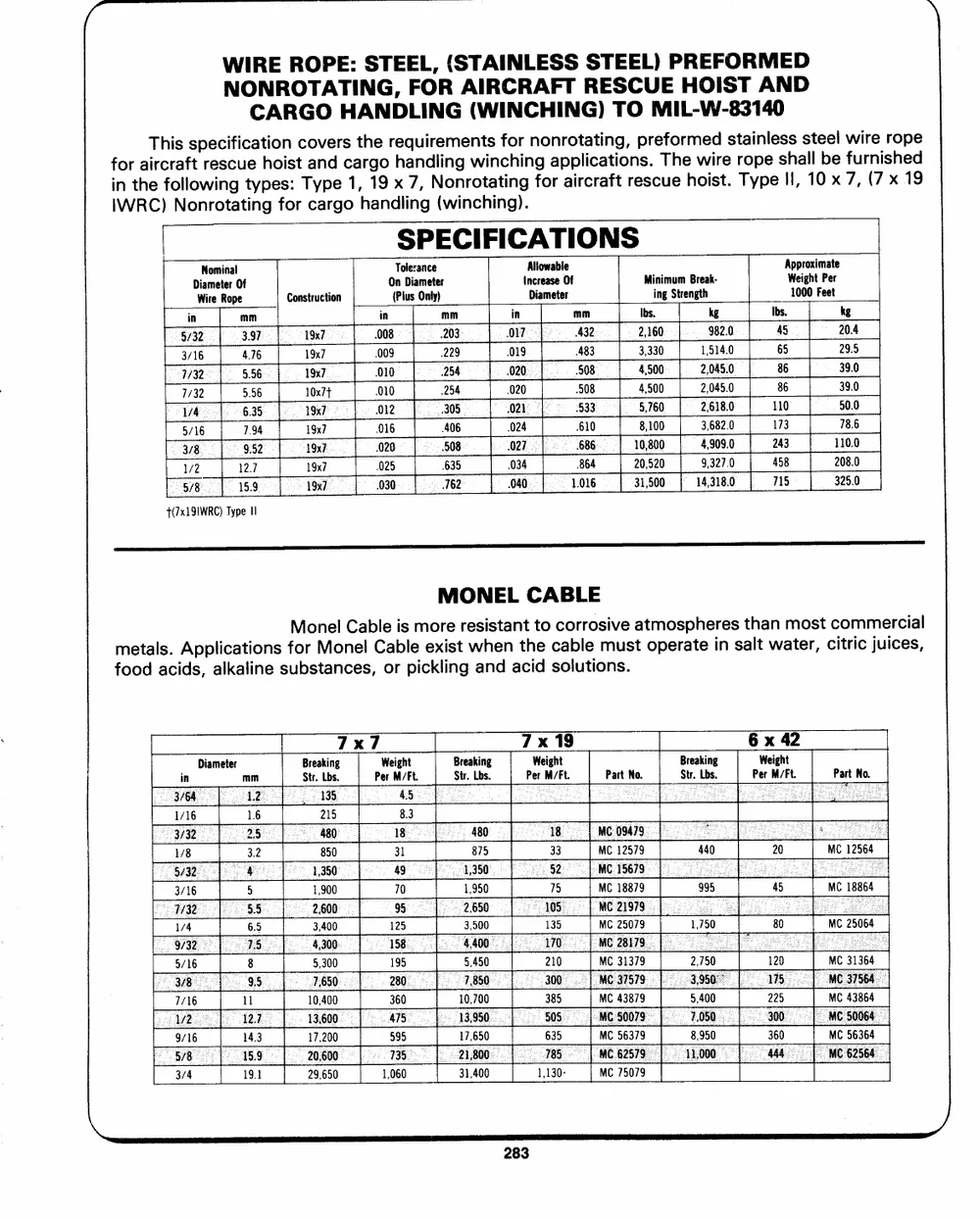
WIRE ROPE: STEEL, (STAINLESS STEEL) PREFORMED wire rope
NOCNARROTGAOTHIANGN,DLFIONRGA(IWRICNRCAHFITNGR)ETSOCUMEILH-OWI-S83T1A40ND furnished
fionrtahiTerhcfirosalflstopreweciisnfgciucteaytphieoosin:stcToayvnpedersc1a,trh1ge9orxheaq7n,udilNrioennmgreonwttiasntcfihonrignnfgoonrarpoapitlraictcriaantfgito,rnsep.srceTufheoerhmowieisdrte.strTaoyipnpeleessHhs,alsl1te0bexel 7, (7 x 19
IWRC) Nonrotating for cargo handling (winching).
| SPECIFICATIONS AWp1ep0ir0go0hxtiFmePaeettre
DWiNiaromemeitRneoarlpOef OT(noPllDuesiraaOmnnecltyee)r AInlDcliroaewmaeastbeelrOef
Construction MiinnigmSutmrenBgrtehak- Ibs. kg
mm 19x7 in mm in mm Ibs. kg
in 008 203 7 432 2,160 982.0 45 20.4
5/32 3.97 19x7
3/16 4.76 1Sx/ .009 229 019 483 3,330 1,514.0 65 29.5
10x7t 010 254 .020 .508 4,500 2,045.0 86 39.0
77/32 5.56 19x7 010 254 .020 508 4,500 2,045.0 86 39.0
7/32 5.56 19x7
1/4 6.35 19x7 912 305 021 533 5,760 2,618.0 110 50.0
19x7 016 406 024 610 8,100 3,682.0 173 78.6
5/16 7.94 19x7 020 508 O27 686 16,800 4,909.0 243 110.0
3/8 9/52
1/2 12.7 025 635 034 864 20,520 9,327.0 458 208.0
030 162 040 1.016 31,500 14,318.0 715 325.0
"5/8 15.9
T(7x191WRC) Type Il
MONEL CABLE commercial
corrosive atmospheres than most citric juices,
metals. Applications fMoornMeolnCealblCeabilsemoexriestrweshiestnantthteo cable must operate in salt water,
food acids, alkaline substances, or pickling and acid solutions.
7x Weight Breaking x Breaking x
Breaking Per M/Ft. Str. Lbs. Weight Str. Lbs. Weight
in Diameter mm Str. Lbs. Per M/Ft. Part No. Per M/Ft. Part No.
215 8.3 MC 12564
MC 18864
850 31 MC 12579 MC 25064
MC 18879
49 MC 25079 MC 31364
MC 43864
1,900 70 MC 31379
MC 43879 MC 56364
3,400 125
MC 56379
5,300 195 MC 75079
10,400 360
17,200 595
29,650
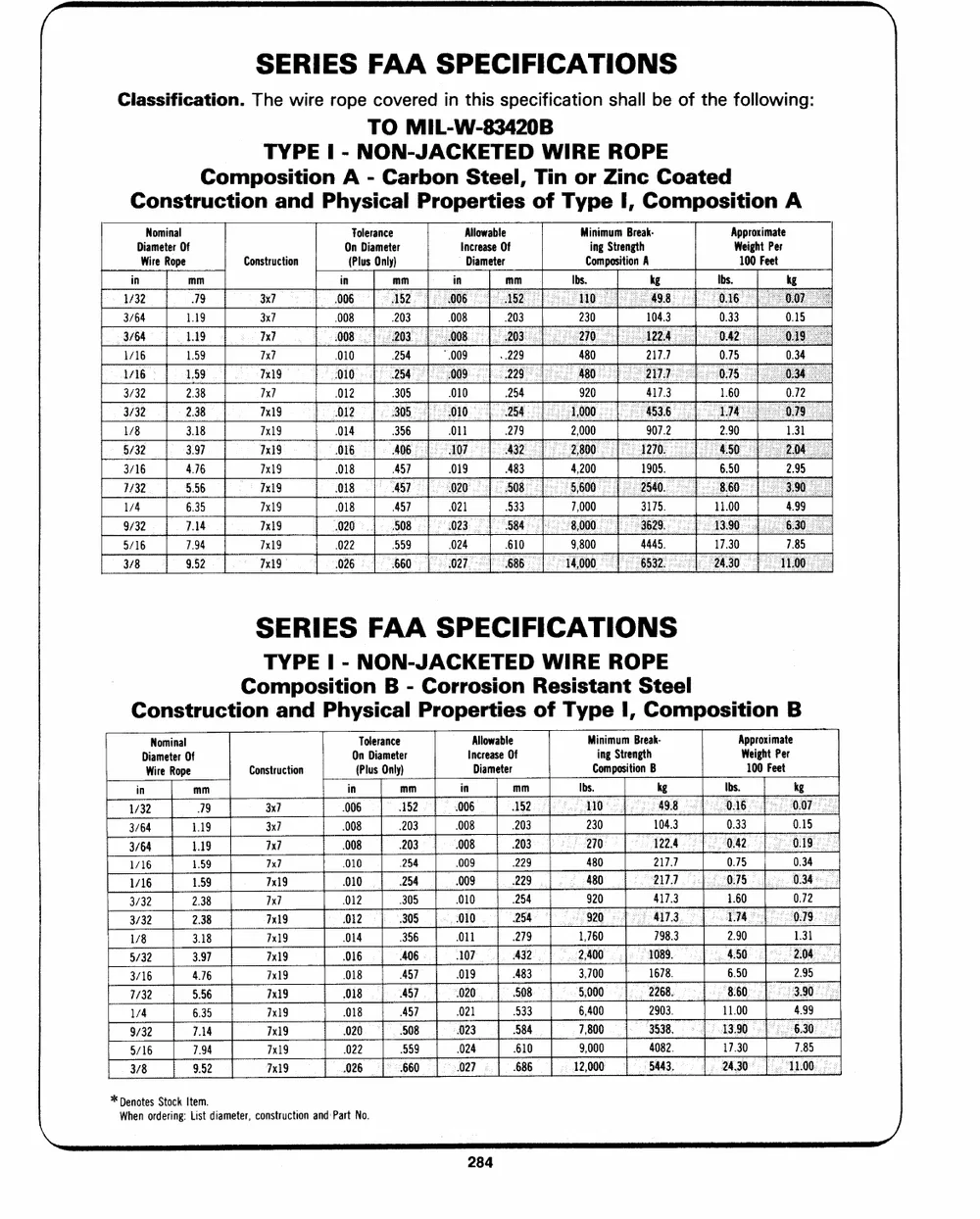
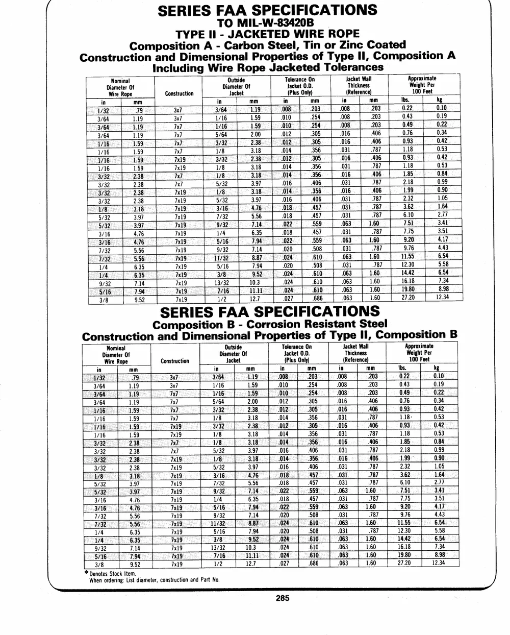
SERIES FAA SPECIFICATIONS
Classification. The wire rope covered in this specification shall be of the following:
TO MIL-W-83420B
TYPE I - NON-JACKETED WIRE ROPE
Composition A - Carbon Steel, Tin or Zinc Coated
Construction and Physical Properties of Type I, Composition A
Nominal Construction Tolerance Allowable Minimum Break- Approximate
Diameter Of On Diameter Increase Of ing Strength Weight Per
Wire Rope 3x7 (Plus Only) Diameter Composition A
3x7 100 Feet
7x]
in mm 7x7 in mm in mm Ibs. kg Ibs. kg
1/32 . 7x7
3/64 .008 .203 .008 .203 230 104.3 0.33 0.15
1/16 010 254 *,009 ..229 480 217.7 0.75 0.34
1/16 0
3/32 012 305 .010 254 920 417.3 1.60 0.72
3/32
1/8 014 396 O11 279 907.2 2.90 131
018 457 .019 483 1905. 6.50 2.95
.018 457 021 933 3175. 11.00 4.99
4445.
022 999 024 610 17.30 7.85
SERIES FAA SPECIFICATIONS
TYPE | - NON-JACKETED WIRE ROPE
Composition B - Corrosion Resistant Steel
Construction and Physical Properties of Type I, Composition B
Nominal Construction Tolerance Allowable Minimum Break- Approximate
Diameter Of On Diameter Increase Of ing Strength Weight Per
Wire Rope 3x7 (Plus Only) Diameter Composition B 100 Feet
3x7
in mm ix/ in mm in mm Ibs. kg Ibs. kg
7x7
1/32 19 7x19 006 452 606 1�2 0 49.8 0:16 0.07
7x7 0.33 0.15
3/64 1.19 7x19 .008 .203 .008 .203 230 104.3 0.19
7x19 122.4 0.42
3/64 115 7x19 .008 203 008 203 270
7x19
1/16 1.59 7x19 010 254 .009 229 480 217.7 0.75 0.34
1/16 1.59 7x19 010 254 008 229 480 2177 0.75 0.34
1.60 0.72
3/32 2.38 7x19 012 305 .010 254 920 417.3 Lia 0.79
920 417.3
3/32 2.38 7x19 G12 305 O10 254 1,760 798.3 2.90 1.31
7x19 014 .356 011 279 2,400 1089.
1/8 3.18 A32 4.50 2.04
3.97 016 -A06 107
5/32 57 019 483 3,700 ~ 1678. 6.50 2.95
3/16 4.76 018
7/32 5.56 018 457 020 508 5,000 2268. 8�60 3.90
6.35 018 AS] 021 533 6,400 2903. 11.00 4.99
1/4
9/32 7.14 020 508 023 384 7,800 3538. 2 A390 6.30
5/16 7.94 022 559 024 610 17.30 7.85
9,000 4082.
11:00
3/8 9.52 026 660 027 686 12,000 5443. 24.30
N * Denotes Stock Item.
When ordering: List diameter, construction and Part No.
SERIES FAA SPECIFICATIONS
TO MIL-W-83420B |
TYPE Il - JACKETED WIRE ROPE
ConstructCioomnpoasnidtDiiomneAns-ioCnaarlboPnroSpteeretli,esTionf or Zinc Coated
Type Il, Composition A
Including Wire Rope Jacketed Tolerances
DiOaJumatecstkieedrteOf TJoalcekreatnc0e.DO.n JTahcikcetknWeaslsl AWpe1pi0rg0ohxtFiemPeaettre
WDiiNaromemeitnearl Of Construction Ibs.
in mm in mm in mm i mm
3/64 . 3x7 . 010 254 . .203 0.43
3/64 . x] 2.00 012 305 . 406 0.76
1/16 . 7x] 3.18 014 356 . 18) 1.18
1/16 . 3.18 014 356 .031 187 1.18
3/32 . 7x7 3.97 016 406 .031 187 2.18
3/32 . 7x19 3.97 016 406 031 187 2.32
5/32 . 7x19 5.56 .018 457 031 187
3/16 . 7x19 1/4 6.35 018 457 .031 187
7/32 ; 7x19 9/32 7.14 020 . 031 187
7.94 020 .. 031 i 187
1/4 . 7x19 5/16
7x19 13/32 10.3 024 610 .063 1.60
063 1.60
686 063
12.7 027
SE7Rx19 IES FAA SPECIFICATIONS 1/2
ConstructionCaonmdpoDsiimteinosnioBna- lCoPrrroopseirotineRseosfisTtyapnet SIIt,eCelomposition B
WDiiNaromemeitneralOf DOiauJmtaesctikeedrteOf TJoalcekreatnc0e.DO.n TJhaickcektneWsasll AWpe1pi0rg0ohxtFiemPeaettre
Construction Ibs.
in mm i mm in mm i mm
1.19 3x7 1.59 010 254 . 203 0.43
1.19 7x] 2.00 012 305 . 406 0.76
1.59 7x] 3.18 014 356 . 787 1.18:
1.59 7x19 3.18 014 356 . 787 1.18
2.38 7x7 3.97 016 406 . 787 2.18
2.38 7x19 3.97 .016 406 . 187 2.32
3.97 7x19 9.96 .018 457 . 787 6.10
4.76 7x19 6.35 018 457 . 187 7.15
5.56 7x19 7.14 .020 008 . 187 9.76
1/4 6.35 7x19 7.94 020 508 . 187
9/32 7.14 7x19 10.3 024 610 - . 1.60
3/8 9.52 7x19 1/2 12.7 027 686 . 1.60
\ * Denotes Stock Item.
When ordering: List diameter, construction and Part No.
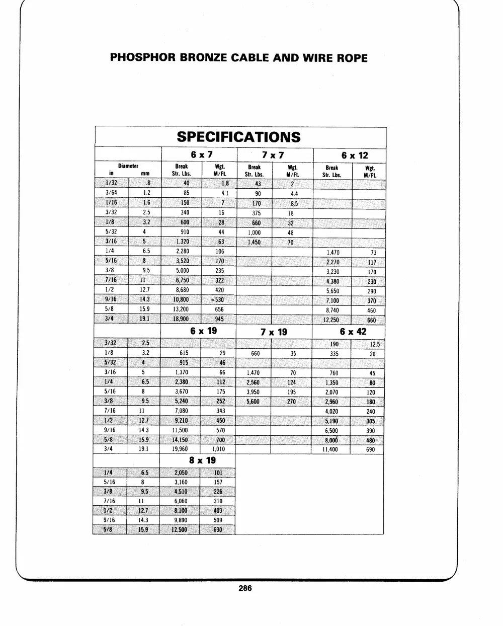
PHOSPHOR BRONZE CABLE AND WIRE ROPE
SPECIFICATIONS
6x7 7x7 6 x 12
Diameter Break Wet. Break Wet. Break Wet.
Str. Lbs. M/Ft. Str. Lbs. M/Ft. Str. Lbs. M/Ft.
in mm
1.2 85 41 90 44
2.5 340 16 378 18
910 44 48
1,370
3,670
7,080
11,500
19,966
\
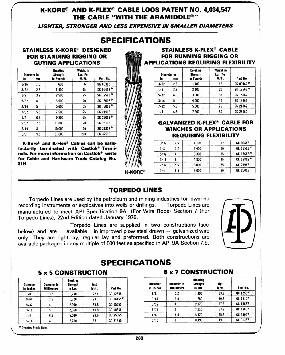
K-KORE� AND K-FLEX� CABLE LOOS PATENT NO. 4,034,547
THE CABLE "WITH THE ARAMIDDLE�"
LIGHTER, STRONGER AND LESS EXPENSIVE IN SMALLER DIAMETERS
SPECIFICATIONS
STAINLESS K-KORE� DESIGNED STAINLESS K-FLEX� CABLE
FOR STANDING RIGGING OR
GUYING APPLICATIONS if FOR RUNNING RIGGING OR
Wve APPLICATIONS REQUIRING FLEXIBILITY
Diameter in Breaking Weight in Diameter in Breaking Weight in
in mm Strength Lbs. Per Part No. in mm Strength Lbs. Per Part No.
16 | 16 in Pounds 3/32 | 25 in Pounds
3/32 | 25 M/Ft. SK 06312 1/8 3.2 M/Ft. SK 09462*
1/8 3.2 600 Sk 0941*2 5/32 | 4 1,100 SK 12562*
5/32 | 4 1,400 6 SK 12512* 3/16 | 5 2,100 12 SK 15662
3/16 | 5 2,500 15 SK 15612* 1732 | 55 3,900 20 SK 18862
7/32 | 55 3,900 25 SK 18812* 1/4 6.5 4,400 35 SK 21962
1/4 6.5 5,600 40 SK 21912 5,500 45 SK 25062
7,500 55 7,300 75
75 SK 25012* 80
9,800
9/32 | 75 95 SK 28112 GALVANIZED K-FLEX� CABLE FOR
5/16 | 8 11,800 Sk 31312* WINCHES OR APPLICATIONS
3/8 95 15,000 120
150 SK 37512 REQUIRING FLEXIBILITY
21,000
K-Kore� and K-Flex� Cables can be satis- 3/32 2.5 1,100 12 "GK 09462
factorily terminated with Castlok� Termi- 1/8 3.2 2,400 20 GK 12562*
nals. For more information on Castlok� write 5/32 4 3,300 5 GK 1566*2
for Cable and Hardware Tools Catalog No. , 3/16 5 4,800 45 CK 1886*2
81H. ETH 7732 | 55 6,000 75 GK 21962
K-KORE� 1/4 6.5 8,000 80 GK 25062
TORPEDO LINES
Torpedo Lines are used by the petroleum and mining industries for lowering
recording instruments or explosives into wells or drillings. Torpedo Lines are
manufactured to meet API Specification 9A, (For Wire Rope) Section 7 (For
Torpedo Lines), 22nd Edition dated January 1976.
Torpedo Lines are supplied in two constructions (see
below) and are available in improved plow steel drawn -- galvanized wire
only. They are right lay, regular lay and preformed. Both constructions are
available packaged in any multiple of 500 feet as specified in API 9A Section 7.9.
SPECIFICATIONS
5 x 5 CONSTRUCTION 5 x 7 CONSTRUCTION
Diameter Diameter in Breaking Wet. Diameter Diameter in Breaking Wat. Part No.
in Inches Millimeters Strength M/ft. Part No. in Inches Millimeters Strength M/{ft.
22.3 GC 12555 23.9 GC 12557
1/8 3.2 in Lbs. 28 GC 1415*5 1/8 32 in Lbs. 30.2 GC 14157
9/64 3.5 34.6 GC 15655 9/64 3.5 37.3 GC 15657
5/32 4 1,290 49.8 GC 18855 5/32 4 1,400 53.8 GC 18857
3/16 5 1,620 88.6 GC 25055 3/16 5 1,760 19459.5 GGCC 2351035577
1/4 65 2,000 138 GC 31355 V4 65 2,170
5/16 8 2,860 5/16 8 3,110
5,030 85,,447900
7,790
\_ *Deetes Stock Item.
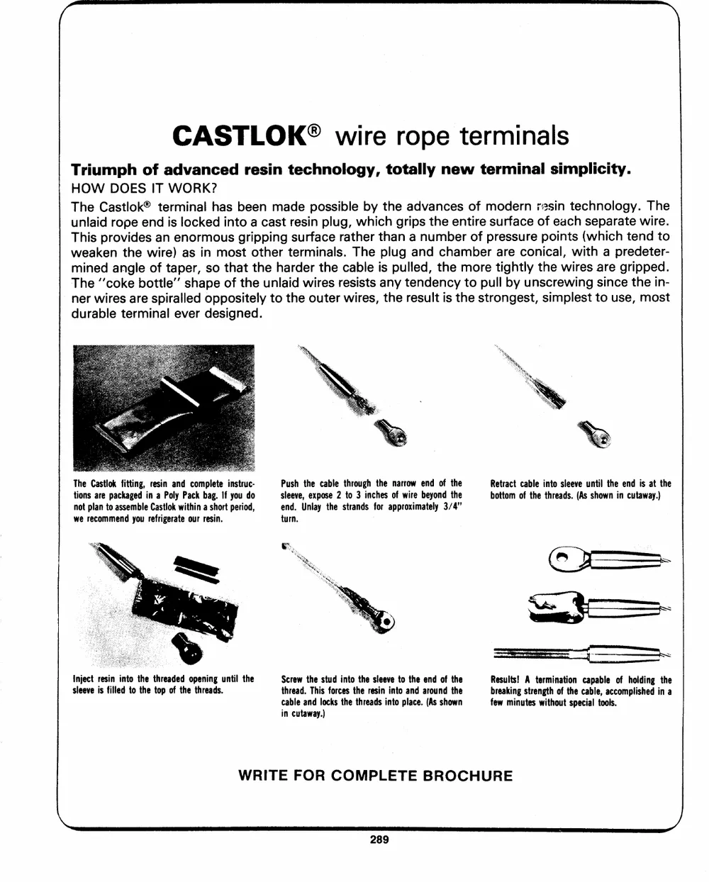
CASTLOK� wire rope terminals
Triumph of advanced resin technology, totally new terminal simplicity.
HOW DOES IT WORK?
The Castlok� terminal has been made possible by the advances of modern ;ssin technology. The
unlaid rope end is locked into a cast resin plug, which grips the entire surface of each separate wire.
This provides an enormous gripping surface rather than a number of pressure points (which tend to
weaken the wire) as in most other terminals. The plug and chamber are conical, with a predeter-
mined angle of taper, so that the harder the cable is pulled, the more tightly the wires are gripped.
The ``coke bottle' shape of the unlaid wires resists any tendency to pull by unscrewing since the in-
ner wires are spiralled oppositely to the outer wires, the result is the strongest, simplest to use, most
durable terminal ever designed.
The Castlok fitting, resin and complete instruc- Push the cable through the narrow end of the Retract cable into sleeve until the end is at the
tions are packaged in a Poly Pack bag. If you do sleeve, expose 2 to 3 inches of wire beyond the bottom of the threads. (As shown in cutaway.)
not plan to assemble Castlok within a short period, end. Unlay the strands for approximately 3/4"
we recommend you refrigerate our resin. turn.
Inject resin into the threaded opening until the Screw the stud into the sleeve to the end of the Results! A termination capable of holding the
sleeve is filled to the top of the threads. thread. This forces the resin into and around the breaking strength of the cable, accomplished in a
few minutes without special tools.
cable and locks the threads into place. (As shown
in cutaway.)
WRITE FOR COMPLETE BROCHURE
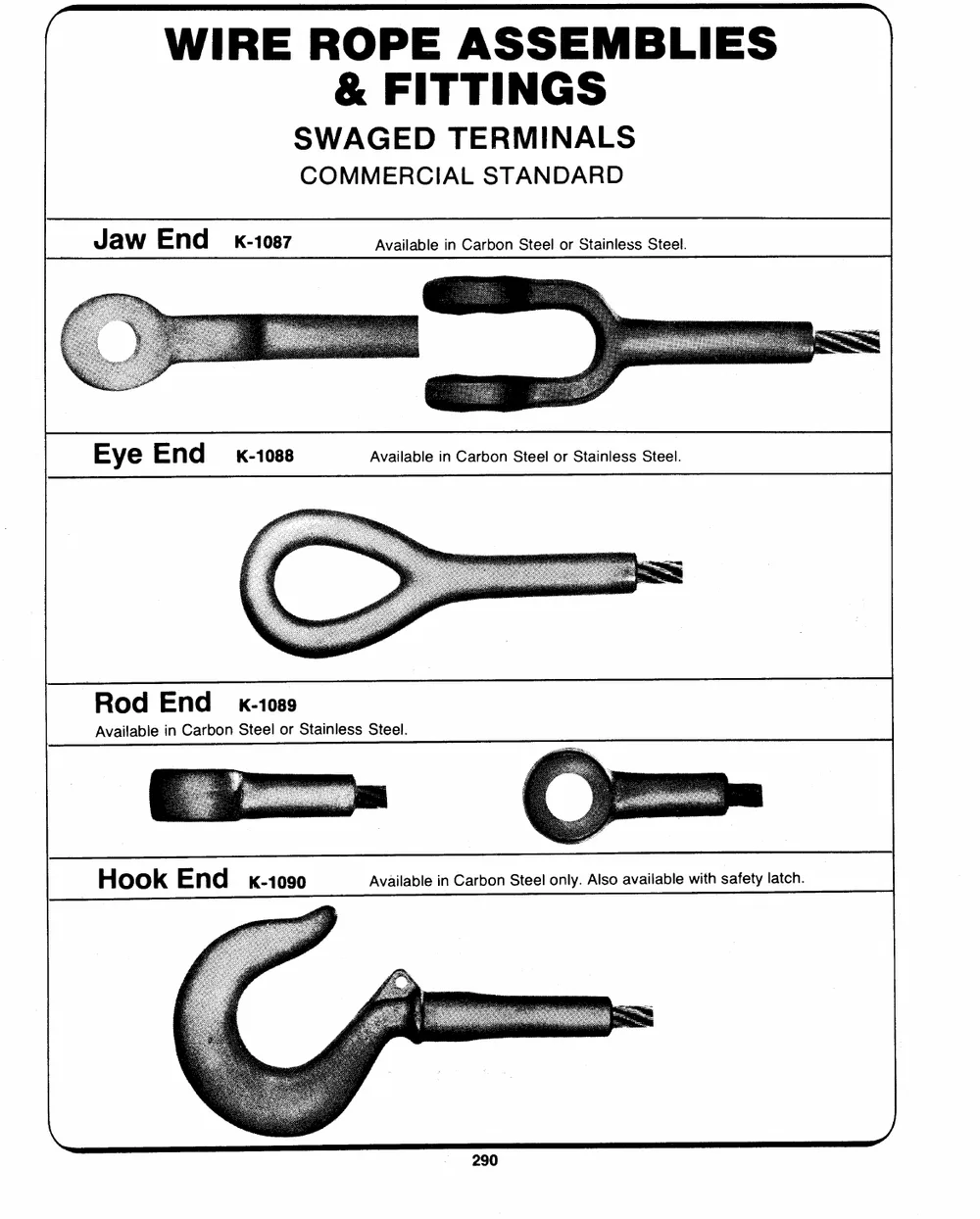
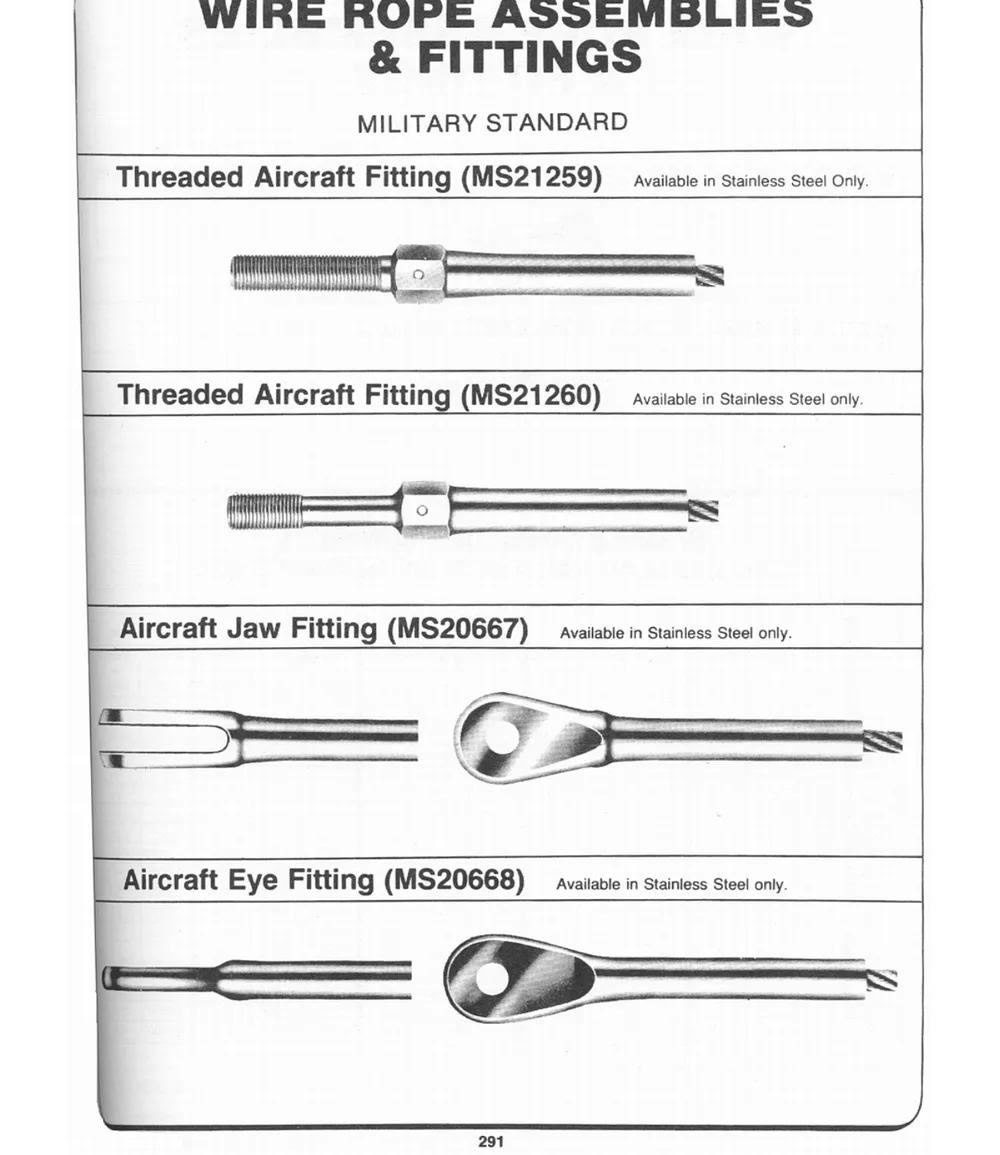
WIRE ROPE ASSEMBLIES
& FITTINGS
SWAGED TERMINALS
COMMERCIAL STANDARD
Jaw End _�-1087 Available in Carbon Steel or Stainless Steel.
Eye End K-1088 Available in Carbon Steel or Stainless Steel.
| Rod End _�-1089
Available in Carbon Steel or Stainless Steel.
Hook End K-1090 Available in Carbon Steel only. Also available with safety latch.
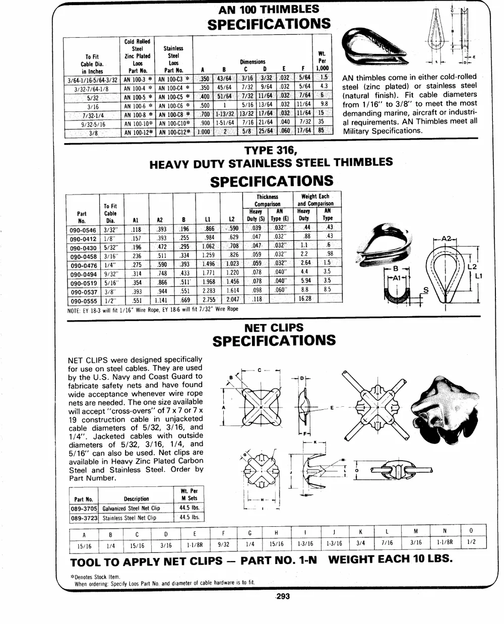
AN 100 THIMBLES
SPECIFICATIONS
Cold Rolled SPStaatLrieotnoelsNleos.s
ZiPnSactrLetoPeollNsaot.ed
CianbTloIenFciDhtieas. AANN 100-4 **| AN 1100-C4 DiCmensionsD Wt. aAsfd(ltnreNeaomretmleautqrnhau1i(dli/zmiri1bnen6lfcmgie"ensinmptstaclohsra)o.i.t3mne/dA8ee")F,Ni'itnaotiTreorchicairtmsbmahtelfebaeterlitenoclrsdoteliishdmanse-medreueomssttltotelersreaeiltdsl-l
110000--610***%|||AAANNN 350 | 45/64 F 1,000
3/32-7/64-1/8 32.| 7/32| 9/64| .032 Military Specifications.
5/64 43
3/16 AN 100-C6 500 5/16 | 13/64 | .032 | 11/64 98
AN 100-C10%* | .900 | 1-51/64| 7/16| 21/64 040 | 7/32 | 35
9/z32-5/16
AN
HEAVY DUTY TYPE 316, THIMBLES
STAINLESS STEEL
PNaor.t CTDaoibalF.iet Al A2 B Ll L2 Thickness (E) | HaDenuWadtevyiyCgohmtpaETraiycAsphNoen.
118 393 196 866.) A3
157 393 255 984 DuHteyaCvo(ymSp)a|riTsyopAne 43
090-0546| 3/32" 196 `412 295 1.062 �590 039 032" AG �
090-0412| 1/8" 236 51) 334 1.259 629 047 032" 88 98
090-0430} 5/32" 208: 047: 032" i
090-0458| 3/16" 323115454 $87946086 3S493L33Y | 111..749796i68 826 059 032" 2.2 331..555
900999000---000454917496||| 951///3412"6"" ~|4 - L2Lti
| 393 944 | 551 2.283 1[41...042252360 | 000577988 | 000344200""" | 524..49644 |
090-0537| 3/8" 1.614 098 .060"" 8.8 8.5
- 090-0555} 1/2" "551 1.141 669 2.755 2.047 118 16.28
NOTE: EY 18-3 will fit 1/16" Wire Rope, EY 18-6 will fit 7/32" Wire Rope
NET CLIPS
SPECIFICATIONS
NET CLIPS were designed specifically
for use on steel cables. They are used
fbaybrtihceatUe.Ss.afeNtayvyneatnsdaCnodashtavGeuafroduntdo
wide acceptance whenever wire rope
nets are needed. The one size available
will accept "cross-overs" of 7 x 7 or 7 x
19 construction cable in unjacketed
cable diameters of 5/32, 3/16, and
1/4". Jacketed cables with outside
diameters of 5/32, 3/16, 1/4, and
5/16" can also be used. Net clips are
available in Heavy Zinc Plated Carbon
Steel and Stainless Steel. Order by
Part Number.
[ Description Wt. Per
Part No. M Sets
445 Ibs.
089-3705) Galvanized Steet Net Clip 44.5 Ibs.
089-3723) Stainless Steel Net Clip
A B C D E F G H | J K L M N 0
15/16 1/4 15/16 3/16 1/4 15/16 1-3/16 1-3/16 3/4 7/16 3/16 1-1/8R 1/2
1-1/8R 9/32
TOOL TO APPLY NET CLIPS -- PART NO. 1-N WEIGHT EACH 10 LBS.
\ *Denotes Stock Item. Loos Part No. and diameter: of cable hardware is to fit.
When ordering: Specify
� w.J. KEATING LIMITED
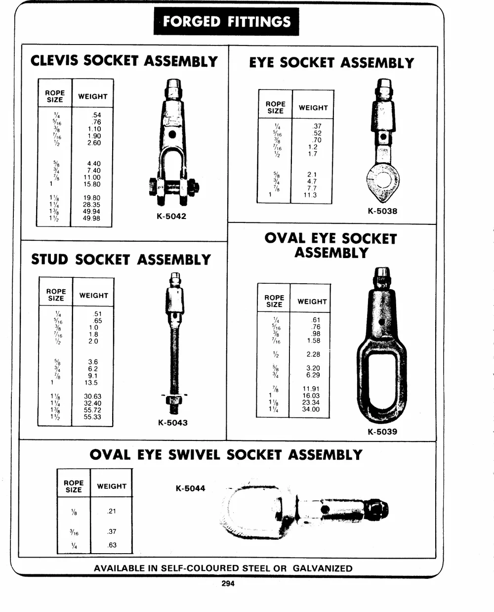
`FORGED FITTINGS
CLEVIS SOCKET ASSEMBLY EYE SOCKET ASSEMBLY
RSOIZPEE WEIGHT RSOIZPEE WEIGHT
"Wy 54
he 76 Ys 37
Va he
he 1.10 52
"5 1.90 Vg 70
2.60 he 1.2
Mo 1.7
Ye 4.40
�,
1% 7.40 Vg 2.1
11.00
1 15.80 Yq 47
's 113
1% 19.80
TY, 28.35
1% 49.94
1%, 49 98
STUD SOCKET ASSEMBLY OVAL EYE SOCKET
ASSEMBLY
RsOizPe.E | WEIGHT ore WEIGHT
st ea Vy 61
7 aoa .
i36 6364 = "py 2.28
i5 p 63..2209
oa | aoe 1% Ai 1 mo] Be16.0
30.63
1iY%f5 �| 85583932 K-5;043 ii , | 3400
OVAL EYE SWIVEL SOCKET ASSEMBLY
BE WEIGHT K-5044
% 21
Ag 37
"sq 63
AVAILABLE IN SELF-COLOURED STEEL OR GALVANIZED
nam W.J. KEATING LIMITED
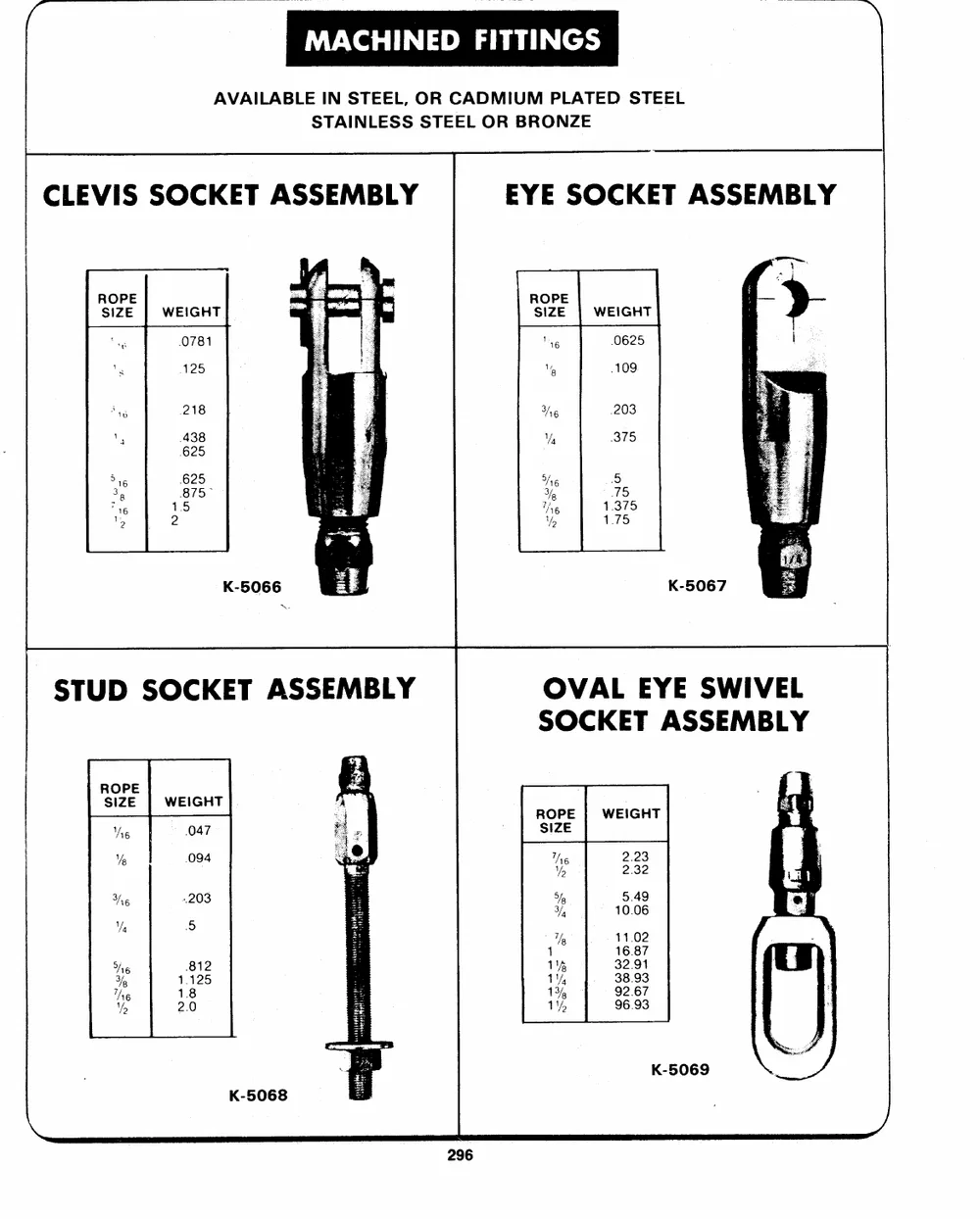
MACHINED FITTINGS :
AVAILABLE IN STEEL, OR CADMIUM PLATED STEEL
STAINLESS STEEL OR BRONZE
CLEVIS SOCKET ASSEMBLY EYE SOCKET ASSEMBLY
ROPE WEIGHT ROPE
SIZE 0781 SIZE | WEIGHT
"6 0625
"% 109
218 ve 203
438 " 375
zTs/he :15.375
`625
7 1.75
K-5067
OVAL EYE SWIVEL
SOCKET ASSEMBLY
ROPE WEIGHT ROPE | WEIGHT
SIZE 047 SIZE
.094
Ae he 2.23
Vp "p 2.32
He 203 5, 5.49
I, 10.06
Va 5 Th 11.02
1 16.87
32.91
He 812 1%
�% 1.125 1" 38.93
134 92.67
The 1.8 1% 96.93
Vo 2.0
K-5069
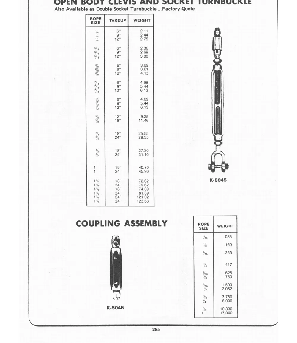
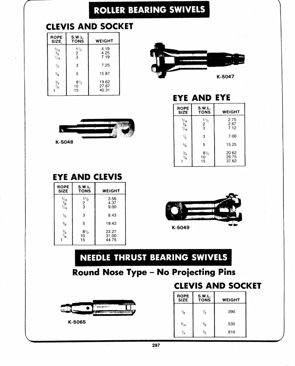
CLEVIS AND SOCKET
ROPE S.W.L. WEIGHT
SIZE, TONS 4.19
4.25
he VV, 7.19
7.25
�, 2
The 3 15.87
" 5 19.62
5),
BY, 27 87
3), 40.31
"Vp 15
EYE AND EYE
ROPE| S.W.L. WEIGHT
SIZE | TONS
22..7857
She 21
Yg 7.12
he 3 7.00
15.25
"sy 3 20.62
26.75
5g 5 37.62
a BY,
"%, 10
1 15
EYE AND CLEVIS
ROPE S.W.L. WEIGHT
SIZE TONS
3.56
He Wy 4.37
Ye 2 9.00
he 3
Vo 3 8.43
fp 5 19.43
23.27
Vg BY 31.00
"hy 10 44.75
1 15
NEEDLE THRUST BEARING SWIVELS
Round Nose Type - No Projecting Pins
CLEVIS AND SOCKET
ROPE | S.W.L. WEIGHT
SIZE TONS
Ye "%o 390
Ne % 535
"a Ys