
Full chapter text (extracted from the original PDF)
Verbatim text extracted from the original chapter PDF (1940–). The original catalog is in English; spec tables may render imperfectly — the PDF remains the authoritative source.
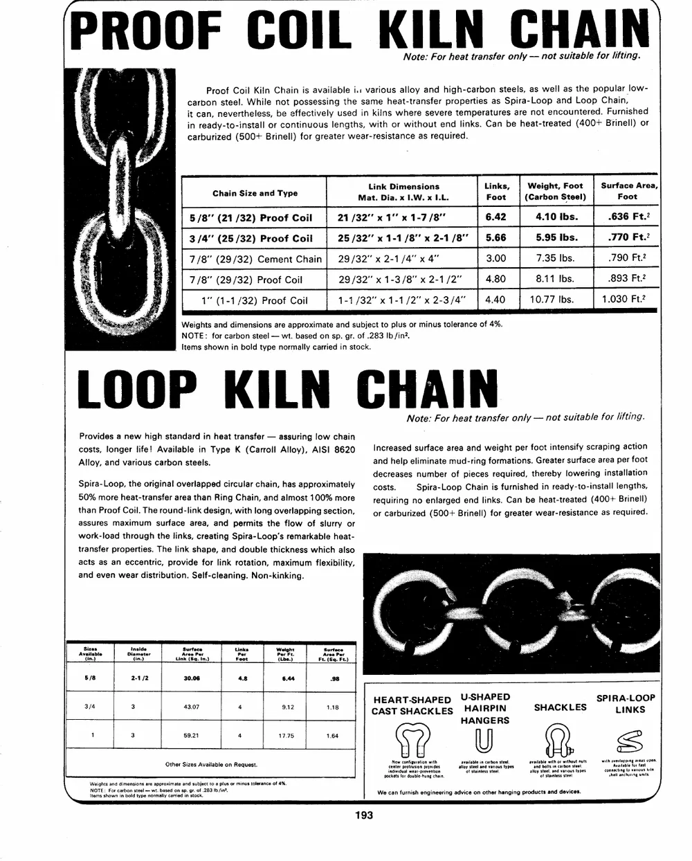
Note: For heat transfer only — not suitable for lifting.
4 Proof Coil Kiln Chain is available i: various alloy and high-carbon steels, as well as the popular low-
carbon steel. While not possessing the same heat-transfer properties as Spira-Loop and Loop Chain,
4 it can, nevertheless, be effectively used in kilns where severe temperatures are not encountered. Furnished
: in ready-to-install or continuous lengths, with or without end links. Can be heat-treated (400+ Brinell) or
: = Es carburized (500+ Brinell) for greater wear-resistance as required.
i ' Chain Si dT Link Dimensions Weight, Foot Surface Area,
: se Mat. Dia. x IW. x LL. (Carbon Steel) Foot
Ea ‘3 on : 5 /8°" (21 /32) Proof Coil 21 /32"" x 1" x 1-7/8” |6.42 | 4.101bs. | -636 Ft.2
; : : 3/4” (25/32) Proof Coil 25 /32°’ x 1-1/8” x 2-1/8” | 5.66 | 5.95 Ibs. | -770 Ft.?
, zs 7/8" (29/32) Cement Chain} 29/32” x 2-1/4" x 4” 7.35 Ibs. .790 Ft.?
it 7/8" (29/32) Proof Coil 29/32” x 1-3/8" x 2-1/2” | 480 | 8itibs. | 893 Ft
*. d 1° (1-1/32) Proof Coil 1-1/32" x 1-1/2” x 2-3/4" 10.77 Ibs. 1.030 Ft.?
ei Weights and dimensions are approximate and subject to plus or minus tolerance of 4%.
: NOTE: for carbon steel — wt. based on sp. gr. of .283 Ib/in?.
Items shown in bold type normally carried in stock.
Note: For heat transfer only — not suitable for lifting.
Provides a new high standard in heat transfer — assuring low chain
costs, longer life! Available in Type K (Carroll Alloy), AISI 8620 Increased surface area and weight per foot intensify scraping action
Alloy, and various carbon steels. and help eliminate mud-ring formations. Greater surface area per foot
. . decreases number of pieces required, thereby lowering installation
Spira-Loop, the original overlapped circular chain, has approximately costs. Spira-Loop Chain is furnished in ready-to-install lengths,
50% more heat-transfer area than Ring Chain, and almost 100% more requiring no enlarged end links. Can be heat-treated (400+ Brinell)
than Proof Coil. The round-link design, with long overlapping section, or carburized (500+ Brinell) for greater wear-resistance as required.
assures maximum surface area, and permits the flow of slurry or
work-load through the links, creating Spira-Loop’s remarkable heat-
transfer properties. The link shape, and double thickness which also
acts as an eccentric, provide for link rotation, maximum flexibility,
and even wear distribution. Self-cleaning. Non-kinking. : . CC
HEART-SHAPED U-SHAPED SPIRA-LOOP
ue = oa = CAST SHACKLES HAIRPIN SHACKLES LINKS
HANGERS
cantor srttoalen provides seats cet SNaiatuton tame Aemdtle or tt
individual wear-prevention of stainless steel. alloy steel, and warious types connecting to various kiln
pockets for double: hung chain. of stauniess steel shell anchoring waits
Weights and dimensions are approximate and subject to a plus or minus tolerance of 4%.
Pec local prarmetenegealch pnp es ata Bike. We can furnish engineering advice on other hanging products and devices.

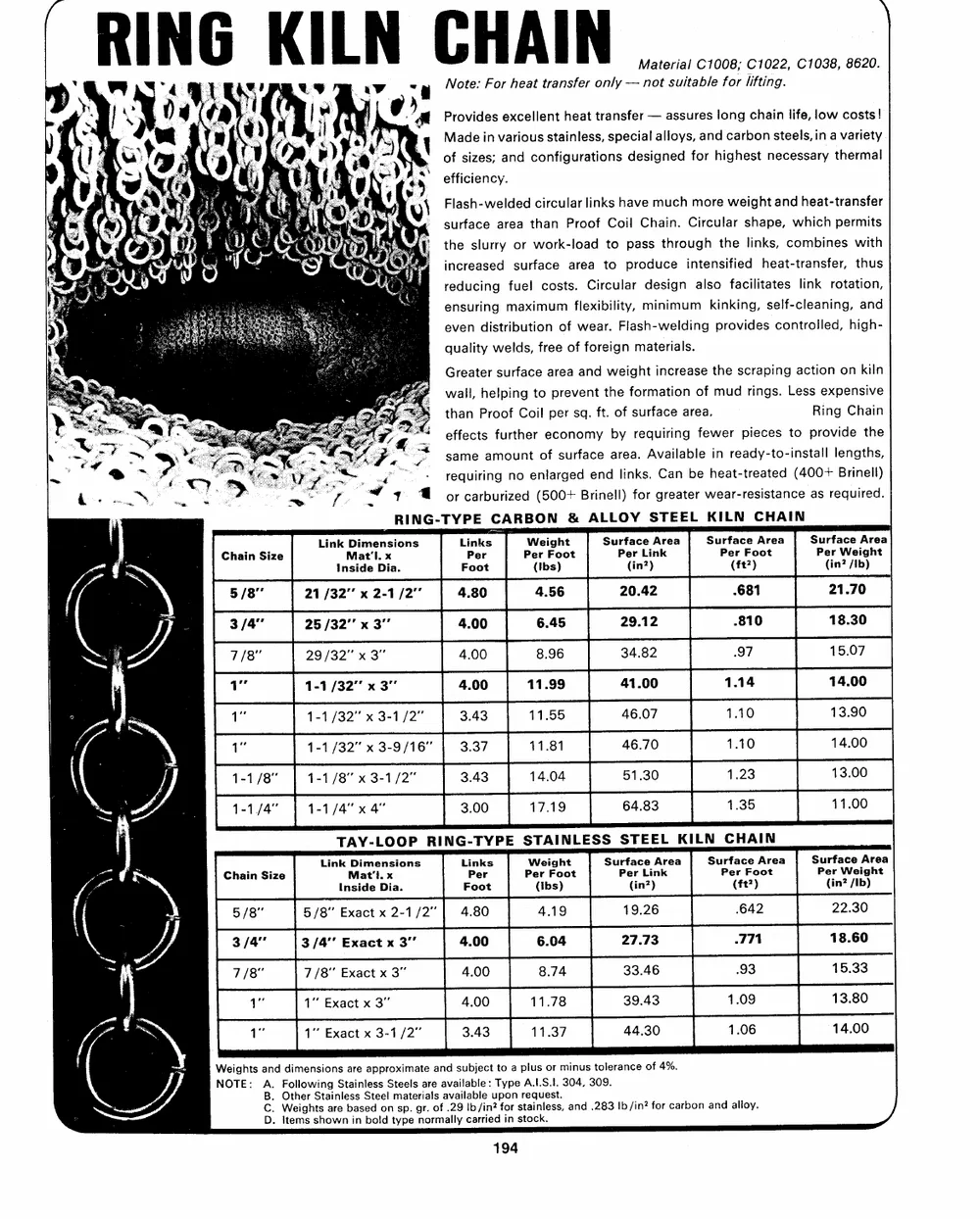
Ri uM 6 K i L a C H Al * Material C1008; C1022, C1038, 8620.
‘ F “4 I L 2] uy Sd Note: For heat transfer only — not suitable for lifting.
Pr te GTN, it tir g \s
< | ‘: 4 ‘a fy) F | 7 ‘ a Provides excellent heat transfer — assures long chain life, low costs!
ay  - ! 8 7 "4 yy 4 \ Made in various stainless, special alloys, and carbon steels, in a variety
iF Se y 9 v | ») @-: of sizes; and configurations designed for highest necessary thermal
R * i wh s ¥ é % {, oh. oY efficiency.

( { *) 1} Ge bi rd y ® V }) Flash-welded circular links have much more weight and heat-transfer
be 2 ( { E 7 ie ee ae A sd Sis surface area than Proof Coil Chain. Circular shape, which permits
) 5) OL ’ YE RMIT the slurry or work-load to pass through the links, combines with

Gh: OU iar o f oC! Wy Oe) increased surface area to produce intensified heat-transfer, thus
UY 9 At ; @i reducing fuel costs. Circular design also facilitates link rotation,
A: Teer een ea ~ ensuring maximum flexibility, minimum kinking, self-cleaning, and
>) 4 By okey te ety: even distribution of wear. Flash-welding provides controlled, high-
He } Bayes Te SE ¢ : quality welds, free of foreign materials.

*f Greater surface area and weight increase the scraping action on kiln

Px. ee . ité a wall, helping to prevent the formation of mud rings. Less expensive

i < =e Pe - Ames than Proof Coil per sq. ft. of surface area, Ring Chain
>} Sn Wear pee A hd, .)

eg . . EOE L ter, vq “effects further economy by requiring fewer pieces to provide the
N or - sy > a ¥ ny sane Bo AF, > same amount of surface area. Available in ready-to-install lengths,
— e@ *7, om me Vy i - requiring no enlarged end links. Can be heat-treated (400+ Brinell)

- WV ww 8 > ~ — < 4 @ orcarburized (500+ Brinell) for greater wear-resistance as required.
j RING-TYPE CARBON & ALLOY STEEL KILN CHAIN
Link Dimensions Links Weight Surface Area Surface Area Surface Area
#. Mat’'l. x Per Per Foot Per Link Per Foot Per Weight
ae — Inside Dia. Foot (Ibs) (in?) (ft?) (in? /Ib)
| pr [evserxsy [400 | tn99 | avoo [uta | 1400
f 1-1 /32” x 3-9/16" 11.81 46.70 14.00
\ y 1-1/8" | 1-1/8" x 3-1/2" 14.04 51.30 13.00
he 2 1-1/4" | 1-1/4" x 4" 17.19 64.83 11.00
ij TAY-LOOP RING-TYPE STAINLESS STEEL KILN CHAIN
ied Ze Link Dimensions Links Weight Surface Area Surface Area Surface Area
S ie Mat'l. x Per Per Foot Per Link Per Foot Per Weight
Inside Dia. Foot (Ibs) (in?) (ft?) (in? /Ib)
; g Weights and dimensions are approximate and subject to a plus or minus tolerance of 4%.
NOTE: A. Following Stainless Steels are available: Type A.I.S.I. 304, 309.
B. Other Stainless Steel materials available upon request.
C. Weights are based on sp. gr. of .29 Ib/in? for stainless, and .283 |b /in? for carbon and alloy.
D. Items shown in bold type normally carried in stock.

SAA
ti = K-4035 | Nie }
BETTER PRODUCTS BETTER PRODUCTS
GREATER EFFICIENCY GREATER EFFICIENCY
LOWER COST LOWER GOST
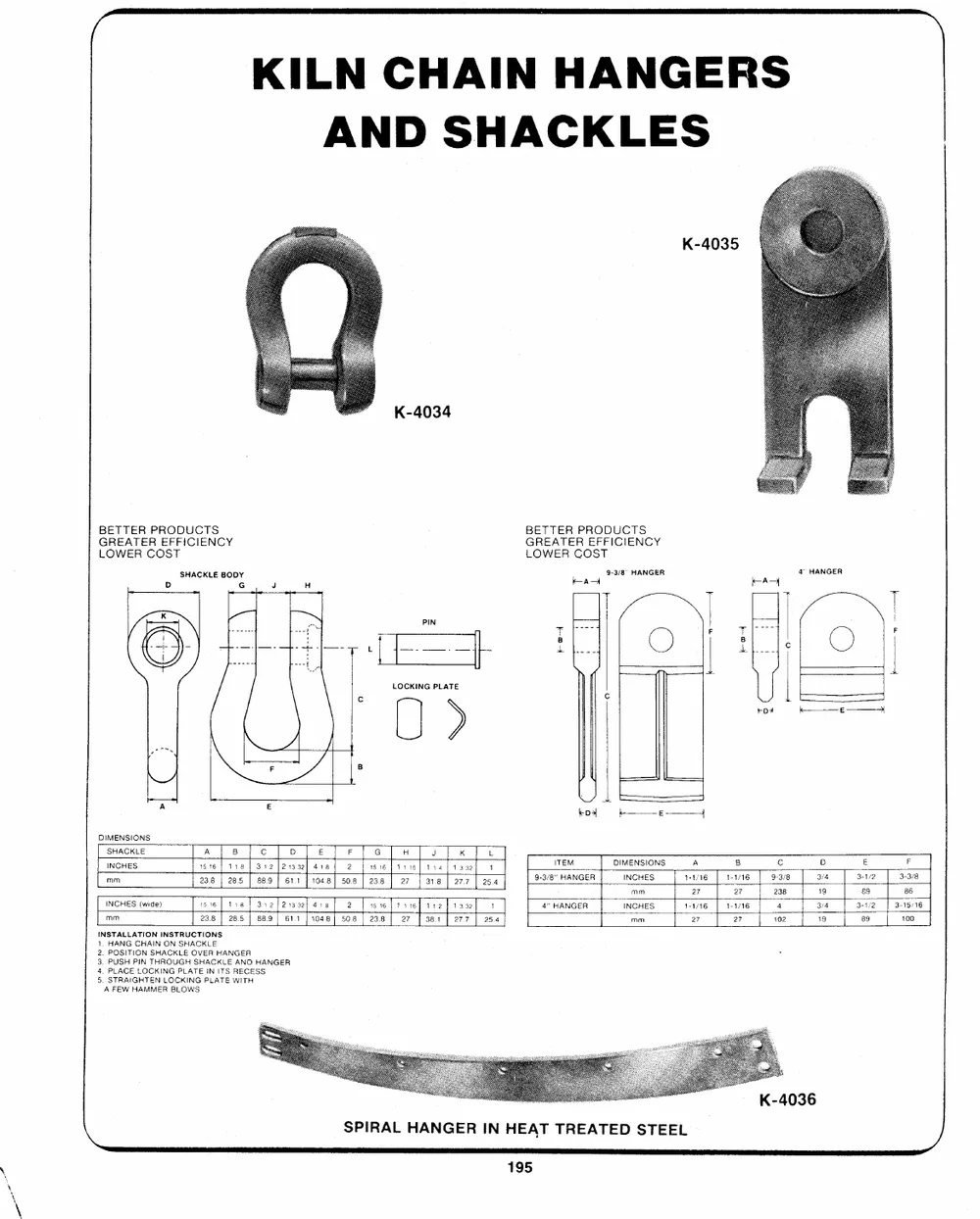
SHACKLE BODY 9-3/8 HANGER 4 HANGER
D G J H ran FAs
| LOCKING PLATE |
gree | |
DIMENSIONS
[sHacce TA Te Po Tote tT eT eT aes [xe]
[erancen | nones [rine [me | «| aa | 08 | Ser |
INSTALLATION INSTRUCTIONS
1, HANG CHAIN ON SHACKLE
2. POSITION SHACKLE OVER HANGER
3. PUSH PIN THROUGH SHACKLE AND HANGER
4. PLACE LOCKING PLATE IN ITS RECESS
5, STRAIGHTEN LOCKING PLATE WITH
A FEW HAMMER BLOWS
eee /_— fs
rs——SCOCO ss i”
SPIRAL HANGER IN HEAT TREATED STEEL

; . oe : ae are LOAD BUCKET FLUSHE
aq A , = am, cat — <n a ag muita. :
= a eat r fs i“ ¥ 5 & cn 2 ie ay a : “ha a
ee oe E %* ai = “ oe dagen
OES SEONG cate ai 7 a. ee
4 21/> a CUR, a
a . & = - _ 2 per ’ a Se , ’ _-