Full chapter text (extracted from the original PDF)
Verbatim text extracted from the original chapter PDF (1940–). The original catalog is in English; spec tables may render imperfectly — the PDF remains the authoritative source.
(MOUNTAINEERING EQUIPMENT >
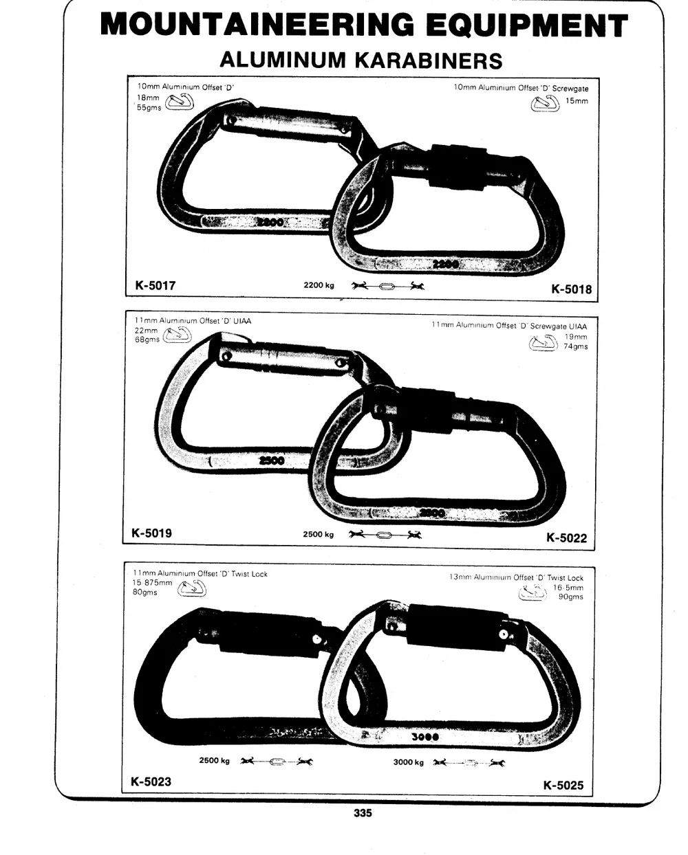
ALUMINUM KARABINERS
10mm Aluminium Offset `D' 10mm AluminiumOffset 'D' Screwgate
18mm ESS) &S 15mm
LY
K-5017 2200kg --u<k>---_Suat K-5018
171mm Aluminium Offset `D' UIAA 11mm Aluminium Offset 'D' Screwgate UIAA
AS) 19mm
2682gmmms & /& >) 74gms
K-5019 2500kg -- uh K-5022
11mm Aluminium Offset `D' Twist Lock 13mm Aluminium Offset `D' Twist Lock
80gms GS 15-875mmAWS (�25S)16:g05gmmms
2500 kg 9 th ---ot 3000 kg Pu Sage
\ K-5023 K-5025 )
MOUNTAINEERING EQUIPMENT
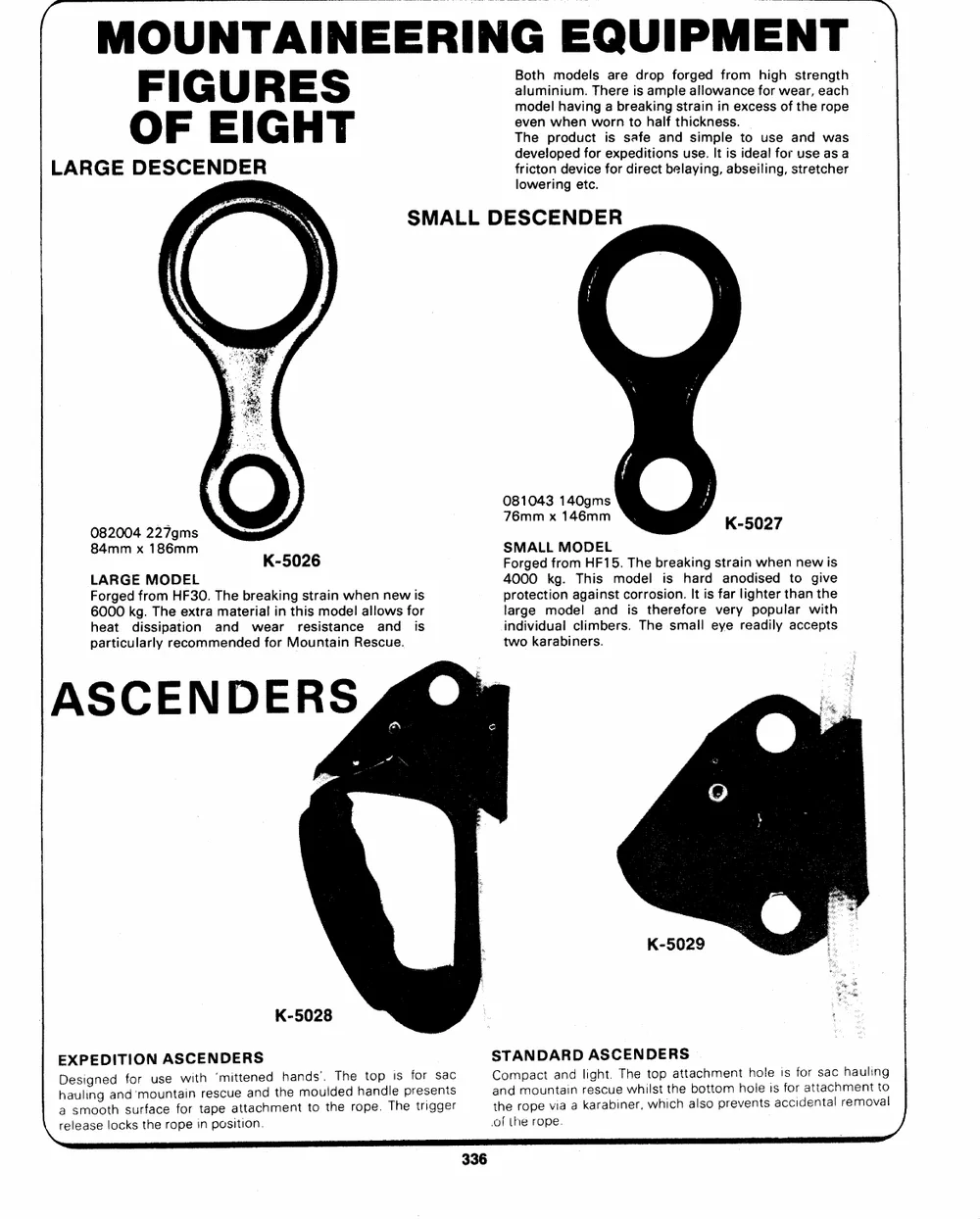
FIGURES Both models are drop forged from high strength
aluminium. There is ample allowance for wear, each
OF EIGHT
model having a breaking strain in excess of the rope
LARGE DESCENDER even when worn to half thickness.
The product is safe and simple to use and was
developed for expeditions use. It is ideal for use as a
fricton device for direct belaying, abseiling, stretcher
lowering etc.
SMALL DESCENDER
082004 227gms K-5026 081043 140gms
84mm x 186mm 76mm x 146mm
LARGE MODEL SMALL MODEL
Forged from HF15. The breaking strain when new is
Forged from HF30. The breaking strain when new is 4000 kg. This model is hard. anodised to give
6000 kg. The extra material in this model allows for protection against corrosion. It is far lighter than the
heat dissipation and wear resistance and is large model and is therefore very popular with
individual climbers. The small eye readily accepts
particularly recommended for Mountain Rescue. two karabiners.
ASCENDERS @y
K-5028
{reEhaDaleXusesPlmaiiEsognneogDetIldahonTcdskfIosu`rOrmtfNohaueucsnAeertoSafpwoiCerintEithrnaNepps`oDecmsuiiEaetttiRttoaenSann.ceddhmtehhenatnmdsot'ou.ltdhTeehderohpateno.dplTeihseprftoerrsiegsngatecsr oSCatfhnoTedmtAhprmeaoNopcruDeotnptAveaia.aRnidnaDrlkiAeagrshSatc.buCieTnEehwrheN,iDltwsohEtpiRtchahSettabalocstohtmpoermnetvheohnlotelseisacifscoirfdoaertnttsaaalcchrhmeaemunoltviantglo
ae
\
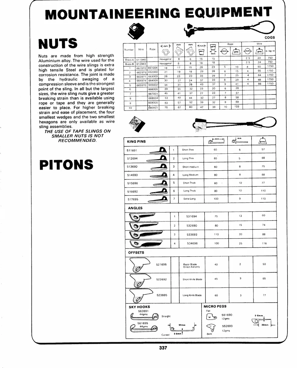
N U TS | mnfe mm mm 2mm F Rope ~< Number Wire RopeHHeexxSaa32i2ggs6g0oo- nnaallE2["826a3Y 77 |S Y2s2r68y0e4 |5 |= m218m85 Gene on ko
bANcchcyoouliorngtumrshspmotritsrtehniuaeseocirnsnteusiiimhroolyemnneadsalirosldsfSoaltyteeut.aeelhnevTieclf.echerw.eaoainmTwnrdshiedwreihasseiilgjtsgiouhihni:esnngpegtsslsdtaitirtsfsroeooemdnferngxagttefdthrsoeheaatr 3a
BBrraa4233tTss_A8ss|1| 66[t6661e1e666s2a1234i9c99997sa744757v1034)2o||[lee666se666rs234o0000o000e0203y6|)||12133f68637e2393| 88�7 | 22i>9o5} | 2a44445e |y|j 22so 660o484 |e1V1j7775e5e5000
9 TD 4
31 381 a3 37 al ae | 1780
point of the sling. in all but the largest 6 ee6005| 39 35 32 23 20 6 26
4 37 27 23
sizes, the wire sling nuts give a greater 7 667001; 45 7 37
e6go04| 53 49 44 32 27 8 58
breaking strain than is available using 8 57 52 39 32
669000 63 9 89
rope or tape and they are generally 9 87 60 47 39 10 133
easier to place. For higher breaking 10 660001] 78
-strain and ease of placement, the four
smallest wedges and the two smaliest
hexagons are only available as wire
sling assemblies.
THE USE OF TAPE SLINGS ON
SMARLELCEORMMNEUNTDSEIDS .NOT
KING PINS we | on
511691 1 Short Thin 60. 5 57
PITONS om512694 2 Long Thin 80 5 68
3 Short mediuin 60 8 75
514693 ------ fd, 4 Long Medium 80 8 88
515696 5 Short Thick 60 - 10 77
516692
6 Long Thick 80 10 110
517695 7 Extra Long 100 9 110
ANGLES
\& > 1 531694 75 13 60
A vail 2 532690 80 15 74
|__
20 88
LS 3 533693 110
4. 534696
OFFSETS
521696 Razor Blade 40 2 50
Direct Aid only
522692 Short Knife Blade 45 3 65
523695 Long Knife Blade 60 3 77
SKY HOOKS MICRO PEGS o2-5a mm
562691 Straight Flat 5152525g1g2mm66ss9903 4 20+mm L_
44 gms >|@Q_95m+m +)le [es=
561695 Curved 2-5mmt BentJ
44gms
~
MOUNTAINEERING EQUIPMENT
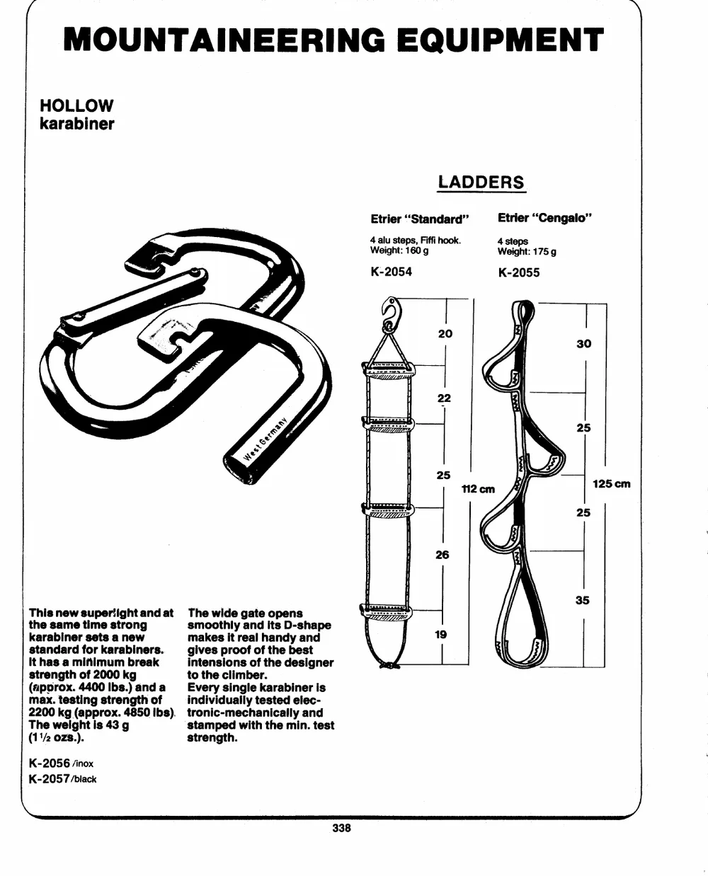
HOLLOW
karabiner
LADDERS
Etrier ``Standard" Etrier "Cengalo"
4 alu steps, Fiffi hook. 4 steps
Weight: 160 g Weight: 175g
K-2054 K-2055
This new super`ight and at The wide gate opens
the same time strong smoothly and its D-shape
karabiner sets a new makes it real handy and
standard for karabiners. gives proof of the best
intensions of the designer
it has a minimum break
to the climber.
strength of 2000 kg Every single karabiner is
(aporox. 4400 Ibs.) and a
max. testing strength of individually tested elec-
2200 kg (approx. 4850 Ibs). tronic-mechanically and
`stamped with the min. test
The weight is 43 g strength.
(11/2 ozs.).
K-2056 /inox
K-2057 /black
\
( MOUNTAINEERING EQUIPMENT |
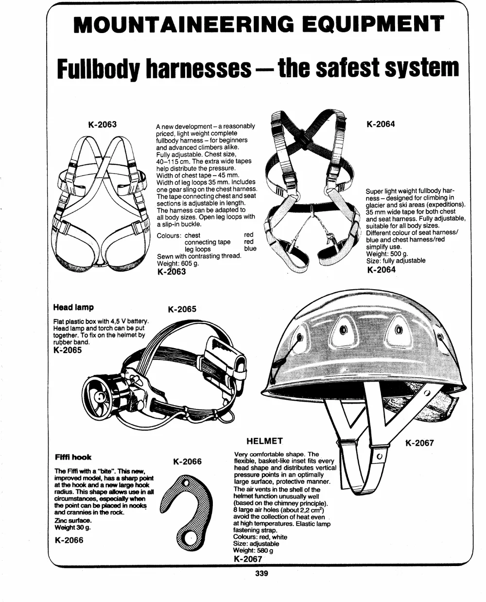
Fullbody harnesses -- the safest system
Anew development -- a reasonably K-2064
priced, light weight complete
fullbody harness -- for beginners Super light weight fullbody har-
and advanced climbers alike. ness -- designed for climbing in
Fully adjustable. Chest size, glacier and ski areas (expeditions).
40-115 cm. The extra wide tapes 35 mm wide tape for both chest
help distribute the pressure. / and seat harness. Fully adjustable,
Width of chest tape -- 45 mm. 4; sDuiiftfearbelnetfcorolaollurboofdysesaitzehsa.rness/
Width of leg loops 35 mm. Includes
one gear sling on the chest harness.
The tape connecting chest and seat
sections is adjustable in length.
The harness can be adapted to
all body sizes. Open leg loops with
a slip-in buckle.
Colours: chest red blue and chest harness/red
connecting tape red simplify use.
leg loops biue
Sewn with contrasting thread. Weight: 500 g.
Weight: 605 g. Size: fully adjustable
K-2063 K-2064
Head lamp
Flat plastic box with 4,5 V battery.
Head lamp and torch can be put
together. To fix on the helmet by
rubber band.
K-2065
Fiffi hook K-2066 HELMET
TheFiffi with a "biTthies n"e. w, Very comfortable shape. The
imp modr el,ho asav shae rp pod int
atthe hookand a new largehook flexible, basket-like inset fits every
radius. This shape allowsuse in all head shape and distributes vertical
circumstances,especially when pressure points in an optimally
thepointcanbeplaced in nooks large surface, protective manner.
andcraninnthi e re ocs k. The air vents in the shell of the
ZWienicgh sutr3 fa0c9 e. . helmet function unusually well
(based on the chimney principle).
_ 8 large air holes (about 2,2 cm?)
K-2066 avoid the collection of heat even .
i at high temperatures. Elastic lamp
\ fastening strap.
Colours: red, white
Size: adjustable
Weight: 580 g
K-2067
~
MOUNTAINEERING EQUIPMENT
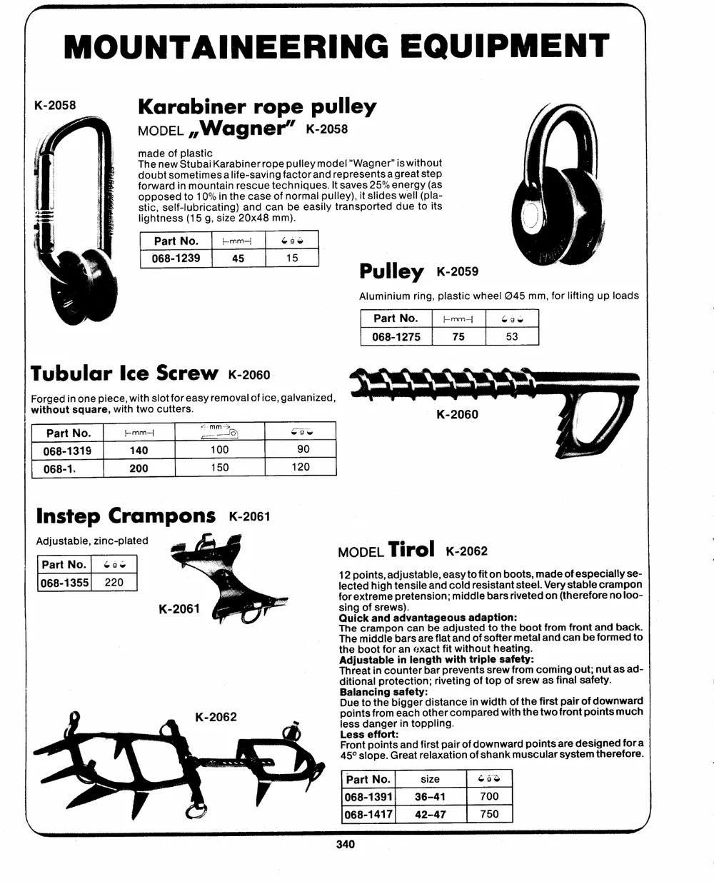
K-2058 Karabiner rope pulley
3 MODEL ,,W| agner" k-2058
made of plastic
The new StubaiKarabiner rope pulley model Wagner' is without
doubt sometimes alife-saving factor and representas great step
forward in mountain rescue techniques. It saves 25% energy (as
opposed to 10% in the case of normal pulley), it slides well (pla-
stic, self-lubricating) and can be easily transported due to its
lightness (15 g, size 20x48 mm).
Part No. E-mm- ece Pulley �-2059
068-1239 45 15
Aluminium ring, plastic wheel @45 mm, for lifting up loads
Part No. Lmm- 696
068-1275 75 53
Tubular Ice Screw �-2060
Forged in one piece, with slot for easy removal of ice, galvanized,
without square, with two cutters.
Part No. [-mm---| emm->9) ooe
068-1319 140 100 90
068-1. 200 150
Instep Crampons �-2061
Adjustable, zinc-plated MODEL Tirol x-2062
Part No.| �so 12 points, adjustable, easy to fit on boots, made of especially se-
068-1355) 220 lected high tensile and cold resistant steel. Very stable crampon
for extreme pretension; middle bars riveted on (therefore no !loo-
sing of srews).
Quick and advantageous adaption:
The crampon can be adjusted to the boot from front and back.
The middle bars are flat and of softer metal and can be formed to
the boot for an exact fit without heating.
ATdihdtrjieuoasntatlainbplrceootuienncttleieronnbg;atrrhipvwreitetivhnegntrotifsptsloerpeswaofffesrtroyem:wcoasmifningalousta;fentuyt. as ad-
BDpoauilenattnsocfitrhnoegmbseiaagfgectehyr:odtihsetracnocempinarwieddtwhiotfh
K-2062 less danger in toppling. the first fpraoinrtopfodinotwsnmwuacrhd
the two
`
Less effort:
rfierlsatxpaatiiroonfodf oswhnawnkarmdupsociunltasrasryesdteesmitghneerdeffoorrea.
Front points and
45� slope. Great
Part No. size 650
068-1391 36-41 700
068-1417 42-47 750 J
r ~
MOUNTAINEERING EQUIPMENT
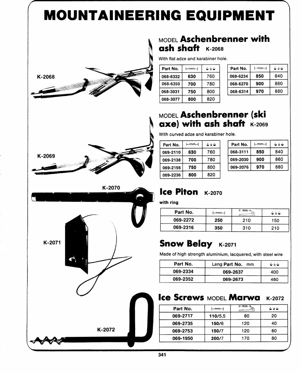
move. Aschenbrenner with
ash shaft �-2063
With flat adze and karabiner hole.
PartNo. | Emm | �36 `PartNo. | Emm | coe
068-6332 630 760 068-6234 850 840
_ 068-6350 | 700 780 068-6270] 900 860
068-3031 | 750 800 068-6314| 970 880
a_i
068-3077 800 820
move. Aschenbrenner (ski
axe) with ash shaft �-2069
With curved adze and karabiner hole.
PartNo. | Emm | G6 Part No. | Emmi | cao
069-2110| 630 760 068-3111] 850 840
069-2138 | 700 780 069-2030! 900 860
069-2156| 750 800 069-2076 | 970 880
069-2236| 800 820
Ice Piton �-2070 m5 68s
with ring L_mm-{ 210 150
310 210
Part No. 250
069-2272
069-2316
Snow Belay �-2071
Made of high strength aluminium, lacquered, with steel wire
Part No. Leng Part No. mm Gae
069-2334 069-2637 400
069-2352 069-2673 480
Ice Screws move. Marwa_ �-2072
Part No. emm--{ --e--m)m9 ea6
069-2717 110/5,5 80 20
069-2735 150/6 120 40
069-2753 150/7 120 60
069-1950 200/7 170 80
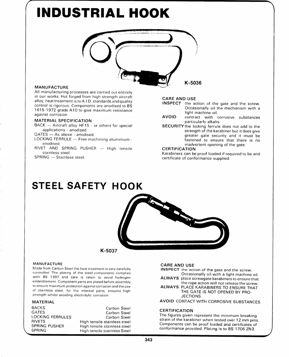
MANUFACTURE K-5036
All manufacturing processes are carried out entirely
in our works. Hot forged from high strength aircraft CARE AND USE
alloy, heat treatment is toA.!.D. standards and quality
control is rigorous. Components are anodised to BS INSPECT the action of the gate and the screw.
1615-1972 grade A10 to give maximum resistance
against corrosion. Occasionally oil the mechanism with a
MATERIAL SPECIFICATION AVOID light machine oil. substances
BACK --Aircraft alloy HF15 - or others for special contract with corrosive
applications - anodised. particularly alkalis.
GATES -- As above - anodised.
LOCKING FERRULE -- Free machining aluminium - SECURITY the locking ferrule does not add to the
anodised. strength of the karabiner but it does give
RIVET AND SPRING PUSHER -- High tensile greater gate security and it must be
stainless steel.
fastened to ensure that there is no
SPRING -- Stainless steel.
inadvertent opening of the gate.
CERTIFICATION
Karabiners can be proof loaded if required to be and
certificate of conformance supplied.
STEEL SAFETY HOOK
K-5037
MANUFACTURE CARE AND USE
INSPECT the action of the gate and the screw.
Made from Carbon Steel the heat treatment is very carefully
controlled. The plating of the steel components complies Occasionally oi! with a light machine oil.
with BS 1397 and care is taken to avoid hydrogen ALWAYS place screwgate karabiners to ensure that
embrittlement. Component parts are plated before assembly
to ensure maximum protection against corrosion and the use the rope action will not release the screw.
of stainless steel, for the internal parts, ensures high ALWAYS PLACE KARABINERS TO ENSURE THAT
strength whilst avoiding electrolylic corrosion.
THE GATE IS NOT OPENED BY PRO-
MATERIAL JECTIONS.
BACKS AVOID CONTACT WITH CORROSIVE SUBSTANCES
GATES
LOCKING FERRULES Carbon Steel CERTIFICATION y,
RIVETS Carbon Steel The figures given represent the minimum breaking
Carbon Steel strain of the karabiner when tested over 12 mm pins.
\__SSPPRRIINNGG PUSHER High tensile stainless steel Components can be proof loaded and certifcates of
High tensile stainless steel conformance provided. Plating is to BS 1706 ZN3.
High tensile stainless Steel
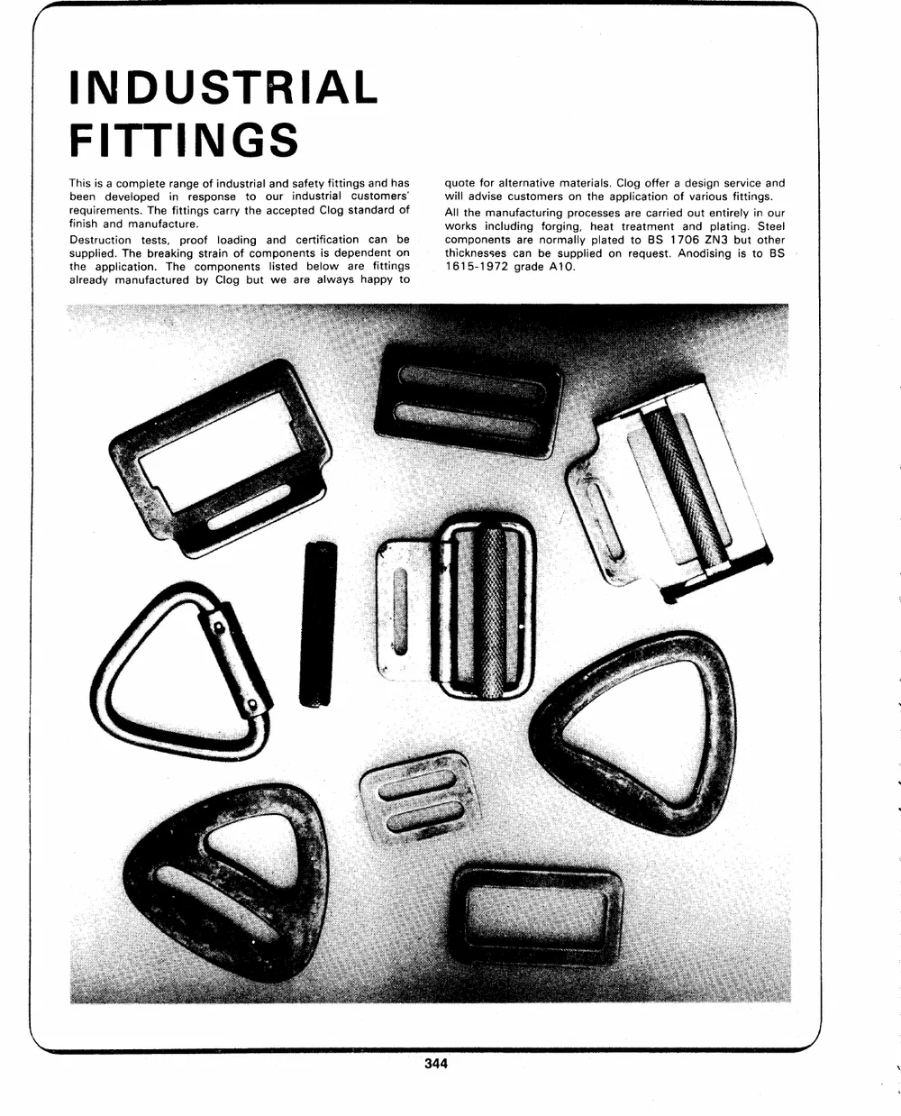
INDUSTRIAL
FITTINGS
This is a complete range of industrial and safety fittings and has quote for alternative materials. Clog offer a design service and
been developed in response to our industrial customers' will advise customers on the application of various fittings.
requirements. The fittings carry the accepted Clog standard of All the manufacturing processes are carried out entirely in our
finish and manufacture. works including forging, heat treatment and plating. Steel
Destruction tests, proof loading and certification can be components are normally plated to BS 1706 ZN3 but other
supplied. The breaking strain of components is dependent on thicknesses can be supplied on request. Anodising is to BS
the application. The components listed below are fittings _ 1615-1972 grade A10.
already manufactured by Clog but we are always happy to
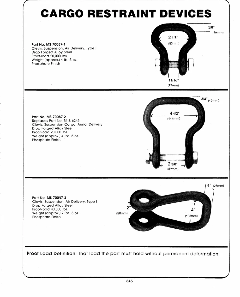
Part No. MS 70087-4 ~\
Clevis, Suspension, Air Delivery, Type|
Drop Forged Alloy Steel 5/8"
Proof-load 20,000 Ibs.
Weight (approx.) 1 Ib. 5 oz. (16mm)
Phosphate Finish
41146"
Part No. MS 70087-2 (47mm)
Replaces Part No. 51 B 6245
Clevis, Suspension Cargo, Aerial Delivery
Drop Forged Alloy Steel
Proof-load 20,000 Ibs.
Weight (approx.) 4 Ibs. 5 oz.
Phosphate Finish
Part No. MS 70087-3 2
Clevis, Suspension, Air Delivery, Type |
(50mm)
PDrrooopf-Flooradge4d0,A0l0l0oyIbSst.eel
Weight (approx.) 7 Ibs. 8 oz.
Phosphate Finish
Proof Load Definition: That load the part must hold without permanent deformation.
\
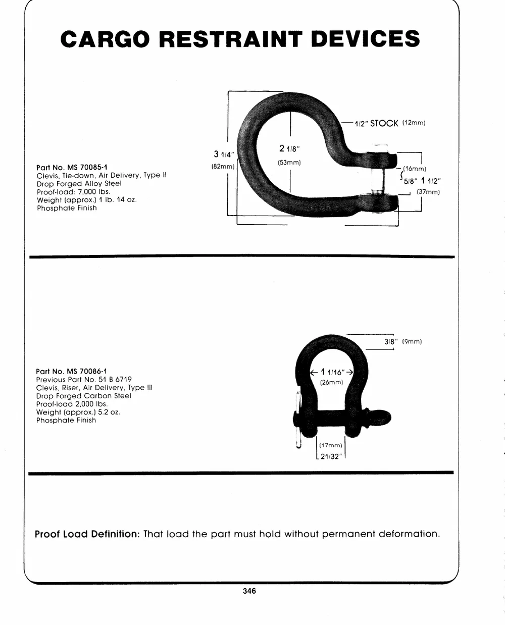
-- 4/2" STOCK (12mm)
Part No. MS 70085-4 (82mm) ~ (46mm)
CDlreovpis,FoTrigee-ddowAnll,oyAirStDeeellivery, Type Il ` (5/18" 11/2"
(37mm)
Proof-load: 7,000 Ibs. |
|
Phosphate Finish Weight (approx.) 1 Ib. 14 oz.
Part No. MS 70086-1
Previous Part No. 51 B 6719
Clevis, Riser, Air Delivery, Type Ill
Drop Forged Carbon Steel
Proof-load 2,000 Ibs.
Weight (approx.) 5.2 oz.
Phosphate Finish
rn
Proof Load Definition: That load the part must hold without permanent deformation.
/)
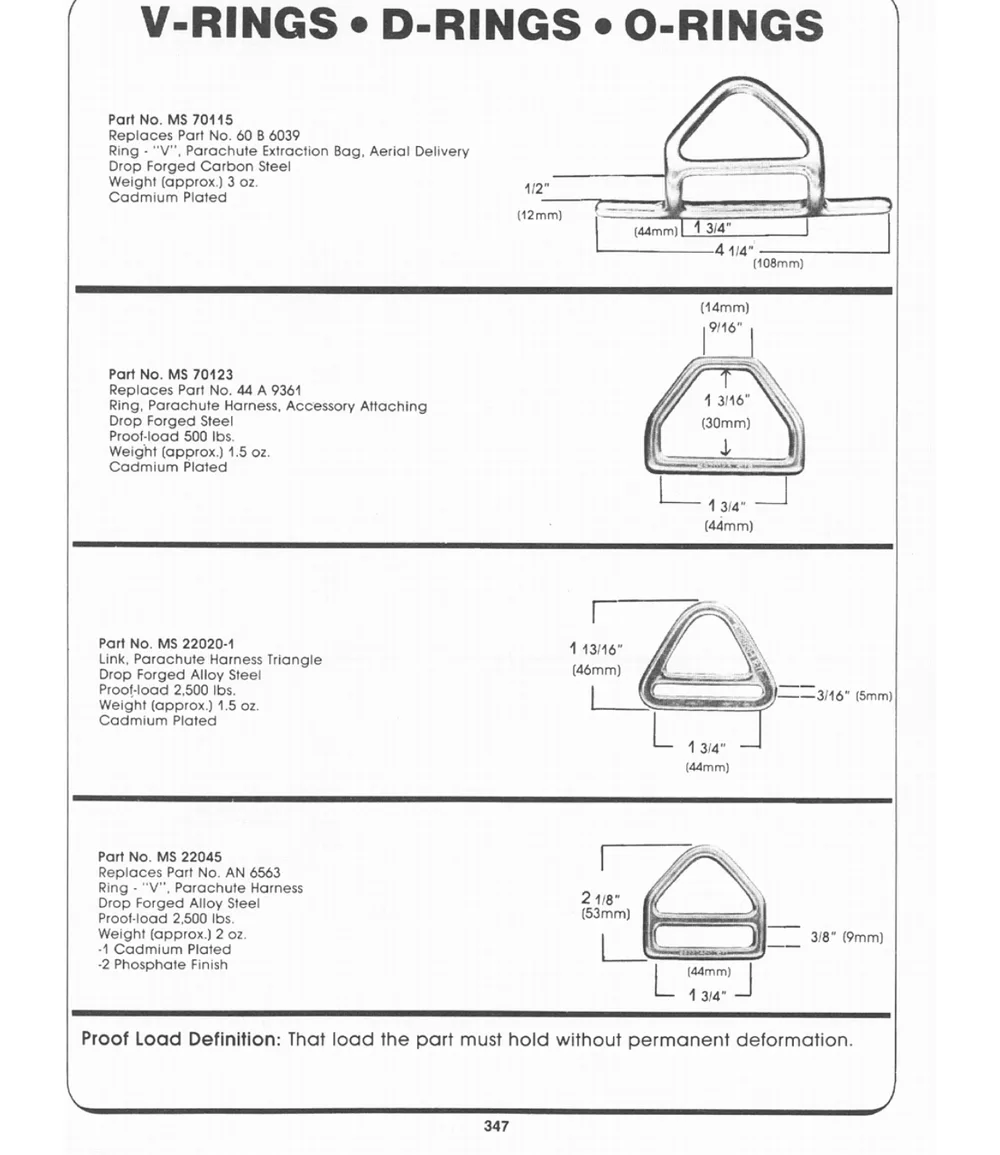
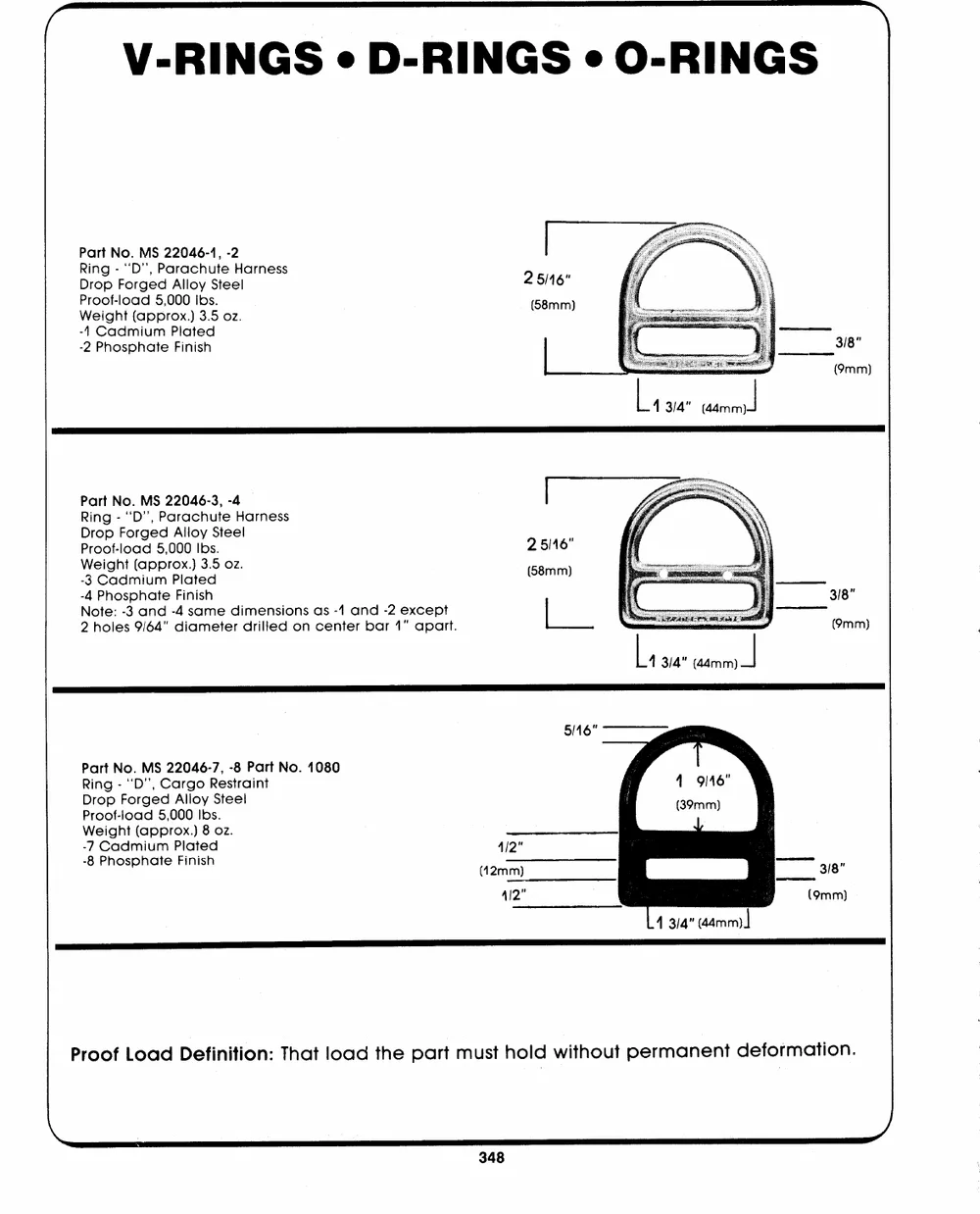
V-RINGS e D-RINGS e O-RINGS | \
Part No. MS 22046-1, -2
Ring - ``D'', Parachute Harness
Drop Forged Alloy Steel
Proof-load 5,000 Ibs.
Weight (approx.) 3.5 oz.
-4 Cadmium Plated
-2 Phosphate Finish
L, 3/4" ainm
Part No. MS 22046-3, -4 2 5/16" 3/8"
Ring - `"`D'', Parachute Harness
(58mm) (9mm)
DPrrooopf-Flooradge5d,0A0l0loIybsS.teel
|
Weight (approx.) 3.5 oz.
-3 Cadmium Plated L, 3/4" ttmm |
-N4otPeh:os-3phaantde -F4isniashme dimensions as -1 and -2 except
2 holes 9/64" diameter drilled on center bar 1" apart.
5/16"
Part No. MS 22046-7, -8 Part No. 1080 4/2" 3/8"
Ring - "`D'', Cargo Restraint (42mm) (9mm)
Drop Forged Alloy Steel
Proof-load 5,000 Ibs. 412" |
Weight (approx.) 8 oz.
-7 Cadmium Plated
-8 Phosphate Finish
4 3/4" (44mm) |
Proof Load Definition: That load the part must hold without permanent deformation.
ee )
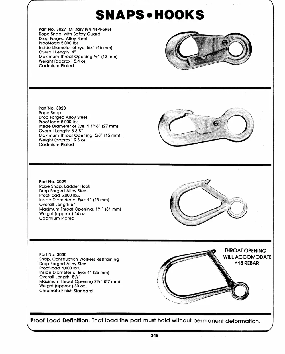
SNAPS e-HOOKS
Part No. 3027 (Military P/N 11-1-598)
Rope Snap, with Safety Guard
Drop Forged Alloy Steel
Proof-load 5,000 Ibs.
inside Diameter of Eye: 5/8" (146 mm)
Overall Length: 4"
Maximum Throat Opening `/2" (42 mm)
Weight (approx.) 5.4 02.
Cadmium Plated
Part'No. 3028
Rope Snap
Drop Forged Alloy Steel
Proof-load 5,000 Ibs.
inside Diameter of Eye: 1 1/46" (27 mm)
Overall Length: 5 3/8"
Maximum Throat Opening: 5/8" (45 mm)
Weight (approx.) 9.3 oz.
Cadmium Plated
Part No. 3029 EE EE
Rope Snap, Ladder Hook
Drop Forged Alloy Steel THROAT OPENING
Proof-load 5,000 Ibs. WILL ACCOMODATE
Inside Diameter of Eye: 1" (25 mm)
Overall Length 6" #48 REBAR
Maximum Throat Opening: 1/4" (34 mm)
Weight (approx.) 14 oz. |
Cadmium Plated
Part No. 3030
snap, Construction Workers Restraining
Drop Forged Alloy Steel
Proof-load 4,000 Ibs.
Inside Diameter of Eye: 1" (25 mm)
Overall Length: 81/2"
Maximum Throat Opening 2'/4" (57 mm)
Weight (approx.) 30 oz.
Chromate Finish Standard
Proof Load Definition: That load the part must hold without permanent deformation.
)
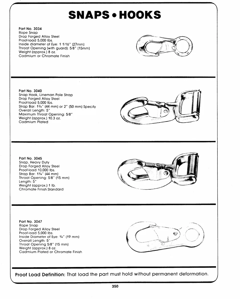
SNAPS �HOOKS
Part No. 3034
Rope Snap
Drop Forged Alloy Steel
Proof-load 5,000 Ibs.
Inside diameter of Eye: 11/16" (27mm)
Throat Opening (with guard): 5/8" (15mm)
Weight {approx.) 8 oz.
Cadmium or Chromate Finish
Part No. 3040
Snap Hook, Lineman Pole Strap
Drop Forged Alloy Steel
Proof-load 5,000 Ibs.
Strap Bar: 13/4" (44 mm) or 2" (50 mm) Specify
Overall Length: 5"
Maximum Throat Opening: 5/8"
Weight (approx.) 10.3 oz.
Cadmium Plated
Part No. 3045
Snap, Heavy Duty
Drop Forged Alloy Steel
Proof-load 10,000 Ibs.
Strap Bar: 13/4" (44 mm)
Throat Opening: 5/8" (45 mm)
Length: 5"
Weight (approx.) 1 Ib.
Chromate Finish Standard
Part No. 3047
Rope Snap
Drop Forged Alloy Steel
Proof-load 5,000 Ibs.
Inside Diameter of Eye: %4" (49 mm)
Overall Length: 5"
Throat Opening 5/8" (145 mm)
Weight (approx.) 8 oz.
Cadmium Plated or Chromate Finish
_ Proot Load Definition: That load the part must hold without permanent deformation. Sy
SNAPS e HOOKS
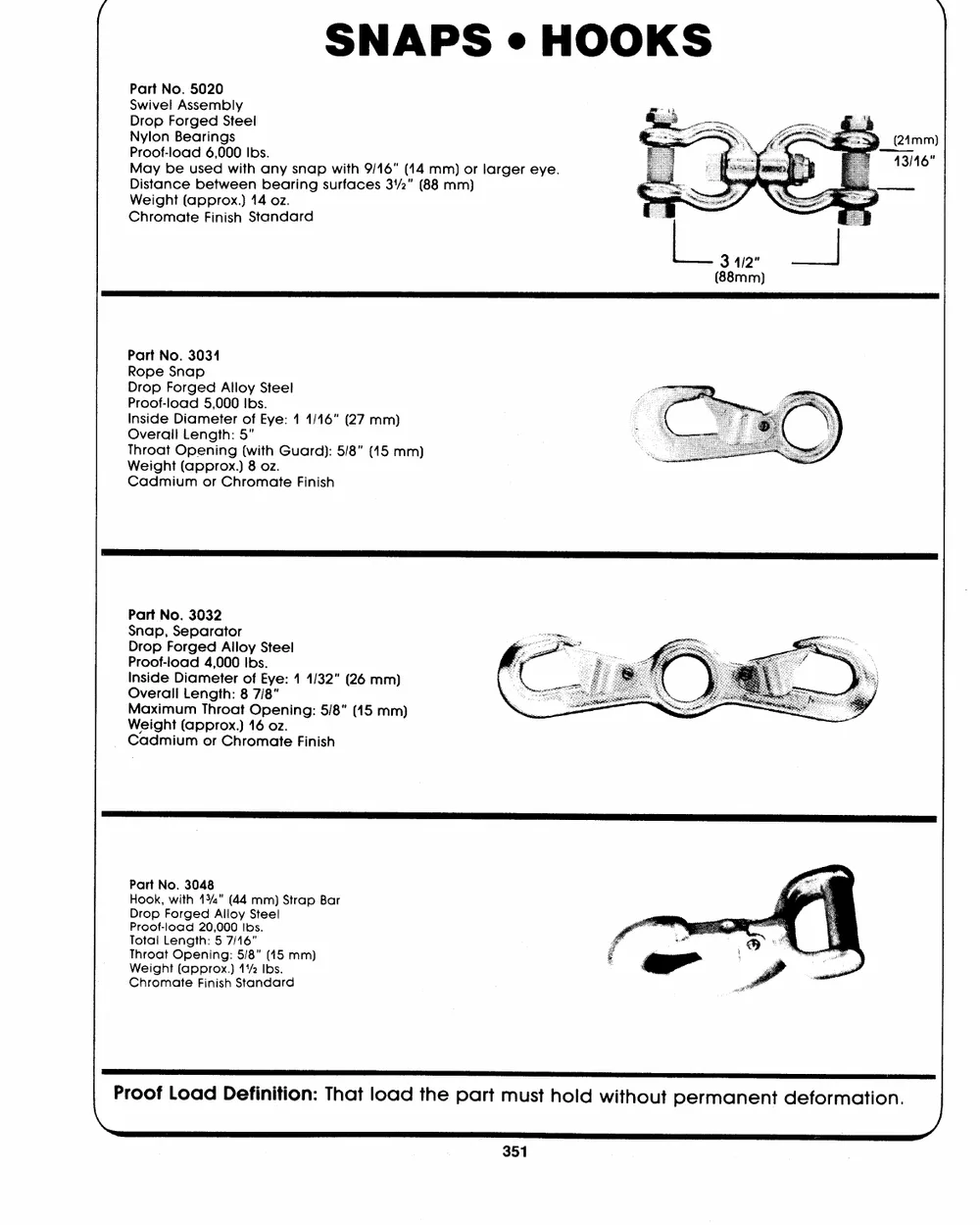
Part No. 5020 " > (24mm)
Swivel Assembly 43/46"
Drop Forged Steel o. P E
Nylon Bearings a _--
Proof-load 6,000 Ibs.
May be used with any snap with 9/16" (14 mm) or larger eye. SE
Distance between bearing surfaces 34/2" (88 mm)
Weight (approx.) 14 oz.
Chromate Finish Standard
Part No. 3034
Rope Snap
Drop Forged Alloy Steel
Proof-load 5,000 Ibs.
Inside Diameter of Eye: 1 1/46" (27 mm)
Overall Length: 5"
Throat Opening (with Guard): 5/8" (45 mm)
Weight (approx.) 8 oz.
Cadmium or Chromate Finish
Part No. 3032
Snap, Separator
Drop Forged Alloy Steel
Proof-load 4,000 Ibs.
Inside Diameter of Eye: 1 1/32" (26 mm)
Overall Length: 8 7/8"
Maximum Throat Opening: 5/8" (45 mm)
Weight (approx.) 16 oz.
Cadmium or Chromate Finish
Part No. 3048
Hook, with 434" (44 mm) Strap Bar
Drop Forged Alloy Steel
Proof-load 20,000 Ibs.
Total Length: 5 7/16"
Throat Opening: 5/8" (45 mm)
Weight (approx.) 11/2 Ibs.
Chromate Finish Standard
Proof Load Definition: That load the part must hold without permanent deformation. )
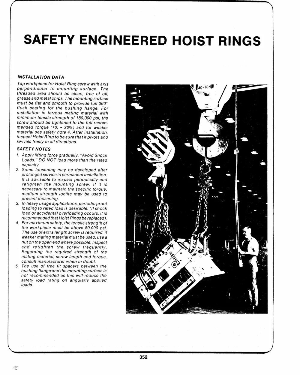
SAFETY ENGINEERED HOIST RINGS
INSTALLATION DATA
Tap workpiece for Hoist Ring screw with axis
perpendicular to mounting surface. The
threaded area should be clean, free of oil,
grease and metal chips. The mounting surface
must be flat and smooth to provide full 360�
flush seating for the bushing flange. For
installation in ferrous mating material with
minimum tensile strength of 180,000 psi, the
screw should be tightened to the full recom-
mended torque (+0, - 20%) and for weaker
material see safety note 4. After installation,
inspect Hoist Ring to be sure th itpa ivot ts and
swivels freely in all directions.
SAFETY NOTES
1. Apply lifting force gradually, "Avoid Shock
Loads." DO NOT load more than the rated
capacity.
2. Some loosening may be developed after
prolonged service in permanent installation.
It is advisable to inspect periodically and
retighten the mounting screw. If it is
necessary to maintain the specific torque,
medium strength loctite may be used to
prevent loosening.
3. In heavy usage applications, periodic proof
loading to rated load is desirable. (1f shock
load or accidental overloading occurs, itis
recommended that Hoist Rings be replaced).
4. For maximum Safety, the tensile strength of
the workpiece must be above 80,000 psi.
The useof extra length screw is required, if
weaker mating material must be used, usea
nut on the open end where possible. Inspect
and retighten the screw frequently.
Regarding the required strength of the
matingmaterial, screw length and torque,
consult manufacturer when in doubt.
5. The use of free fit spacers between the
bushing flange-and the mounting surface is
not recommended as this will reduce the
safety load rating on angularly applied
loads.
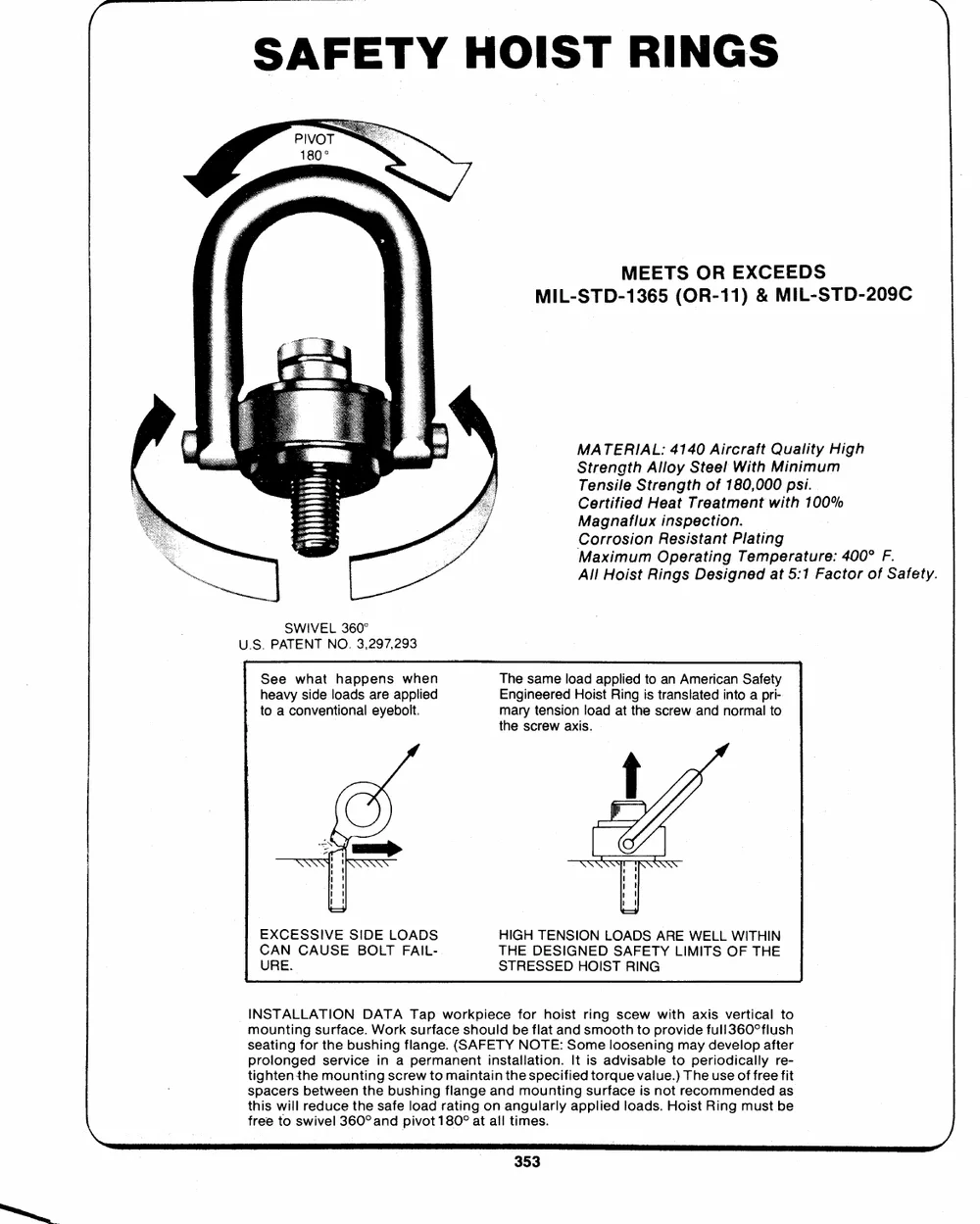
SAFETY HOIST RINGS
MEETS OR EXCEEDS
MIL-STD-1365 (OR-11) & MIL-STD-209C
SWIVEL 360� MATERIAL: 4140 Aircraft Quality High
U.S. PATENT NO. 3,297,293 Strength Alloy Steel With Minimum
Tensile Strength of 180,000 psi.
See what happens when Certified Heat Treatment with 100%
heavy side loads are applied Magnaflux inspection.
to a conventional eyeboit. Corrosion Resistant Plating
Maximum Operating Temperature: 400� F.
All Hoist Rings Designed at 5:1 Factor of Safety.
The same load applied to an American Safety
Engineered Hoist Ring is translated into a pri-
mary tension load at the screw and normal to
the screw axis.
EXCESSIVE SIDE LOADS HIGH TENSION LOADS ARE WELL WITHIN
CAN CAUSE BOLT FAIL- THE DESIGNED SAFETY LIMITS OF THE
URE. STRESSED HOIST RING
INSTALLATION DATA Tap workpiece for hoist ring scew with axis vertical to )
mounting surface. Work surface should be flat and smooth to provide full360�flush
seating for the bushing flange. (SAFETY NOTE: Some loosening may develop after
prolonged service in a permanent installation. It is advisable to periodically re-
tightenthe mounting screw to maintain the specified torque value.) The use of free fit
spacers between the bushing flange and mounting surface is not recommended as
this will reduce the safe load rating on angularly applied loads. Hoist Ring must be
free to swivel 360� and pivot 180� at all times.
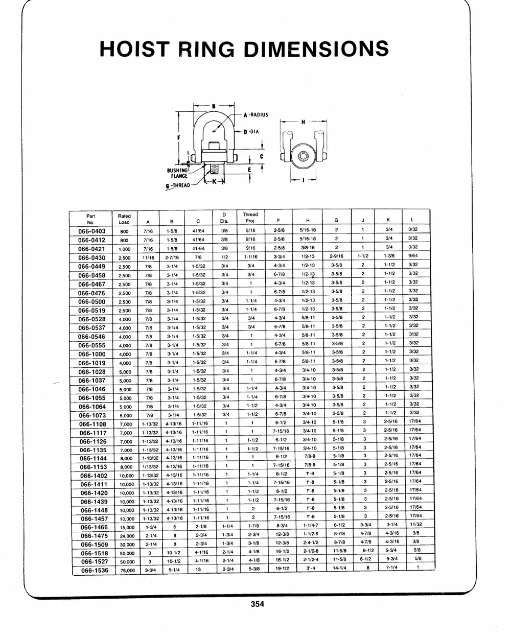
HOIST RING DIMENSIONS
rm--- B
F it. A -RADIUS --
wane Taf | D-DIA 15
tc }
eT HREAD K>
NPaor.t RLaotaedd A B c DiDa. TPhrroeja. d F H G J K L
2-5/8 5/16-18 2 1 3/4 3/32
066-0403 800 7/16 1-5/8 41/64 3/8 5/16 2-5/8 5/16-18 2 1 3/4 3/32
066-0412 800 7/16 1-5/8 41/64 3/8 9/16 2-5/8 2
066-0421 1,000 7/16 1-5/8 41-64 3/8 9/16 3-3/4 3/8-16 2-9/16 1 3/4 3/32
066-0430 2,500 11/16 2-7/16 7/8 1/2 1-1/16 4-3/4 1/2-13 3-5/8 1-1/2 1-9/8 9/64
3/4 6-7/8 1/2-13 3-5/8 2 1-1/2 3/32
066-0449 2,500 7/8 3-1/4 1-5/32 3/4 3/4 4-3/4 1/2-13 3-5/8 2 1-4/2 3/32
066-0458 2,500 7/8 31/4 1-5/32 3/4 1 1/2-13
066-0467 2,500 7/8 3-1/4 1-5/32 3/4 1 6-7/8 1/2-13 3-5/8 2 1-1/2 3/32
066-0476 2,500 7/8 31/4 1-5/32 3/4 1-1/4 4-3/4 1/2-13 3-5/8 2 1-1/2 3/32
066-0500 2,500 7/18 3-1/4 1-5/32 3/4 1-1/4 6-7/8 1/2-13 3-5/8 2 1-1/2 3/32
7/8 3-1/4 1-5/32 3/4 3/4 4-3/4 5/8-11 3-5/8 2 1-1/2 3/32
066-0519 2,500 718 |) 3-1/4 1-5/32 3/4 6-7/8 5/8-11 3-5/8 2 1-1/2 3/32
066-0528 4,000 3/4 4-3/4 5/8-11 3-5/8 2 1-1/2 3/32
066-0537 4,000 7/8 31/4 1-5/32 3/4 6-7/8 5/8-11 35/8
066-0546 4,000 718 3-1/4 1-5/32 3/4 1 4-3/4 5/8-11 3-5/8 2 1-1/2 3/32
066-0555 4,000 718 3-1/4 1-5/32 3/4 1 6-7/8 3-5/8 2 1-1/2 3/32
066-1000 4,000 7/8 31/4 1-5/32 3/4 1-1/4 4-3/4 5/8-11 3-5/8 2 1-1/2 3/32
6-7/8 3/4-10 3-5/8 2 1-1/2 3/32
066-1019 4,000 7/8 3-1/4 1-5/32 3/4 1-1/4 4-3/4 3/4-10 3-5/8 2 4-1/2 3/32
aes 066-1028 5,000 7/8 3-1/4 1-5/32 3/4 1 6-7/8 35/8 2 1-1/2 3/32
066-1037 5,000 7/18 3-1/6 1-5/32 3/4 1 4-3/4 3/4-10 3-5/8 2 1-1/2 3/32
5,000 7/8 31/4 1-5/32 6-7/8 3/4-10 3-5/8
066-1046 5,000 7/8 3-1/4 1-8/32 3/4 1-4/4 6-1/2 3/4-10 55--11//88 2 1-1/2 3/32
_ 066-1055 5,000 7/8 31/4 1-5/32 3/4 1-1/4 7-15/16 5-1/8 2 1-1/2 3/32
5,000 7/8 31/4 3/4 1-1/2 6-1/2 3/4-10 55--11//88 2 1-1/2 3/32
066-1064 11--1133//3322 | 413/16 | 1-5/32 7-61-51//126 33//44-1100 55--11//88 33 22--55//1166 1177//6644
066-1073 7,000 | | 4-13/16 | 1-11/16 3/4 1-1/2 7-61-51//12 6 3/410 5-1/8
066-1108 7,000 | 413/16 { 1-11/16 1 1 7-15/16 37//48-190 5-1/8 3 2-5/16 17/64
066-1117 7,000 | 1-13/32 | 1-11/16 1 1 6-1/2 7r/-8-89 55--11//88
066-1126 78,,000000 || 11--1133//332]2| 441133//1166 | 11--1111//1166 1 1-1/2 7-15/16 r-8 5-1/8 33 22--55//1166 1177//6644
006666--11113454 180,,000000 | 1/13/32 || 441193//1166 | 11--1111//1166 11 1-11 /2 6-1/2 1-8 6-1/2 3 22--55//1166 1177//6644
006666--11145032 | 1-13/32 | 1-11/16 1 1 7-81-53//14 6 1-88 8-7/8 33 2-5/16 17/64
006666--11441210 10,000 | 11--1133//3322 | 413/16 | 1-11/16 1 1-1/4 12-9/8 T-8 811-11--755///888 3 2-5/16 17/64
006666--11443498 10,000 | | 413/16 | 1-11/16 1 1-1/4 111266---311///822 1-1/4-7 14-1/4 3 22--55//1166 17/64
006666--11446567 1100,,000000 } 11--1133//3322|| 44-1133//1166 | 1-11/16 1 1-1/2 19-12 1-1/2-6 3 17/64
066-1475 | 4-13/16 1-11/16 1 1-1/2 222---114//-221--/842 3 2-5/16 17/64
000666666---111555201798 10,000 } 1-13/32 | 2-1/8 1 2 3-4 11/32
_ 066-1536 15,000 1-3/4 6 2-3/4 1 2 3-3/4 3-1/4 3/8
24,000 2-1/4 8 2-3/4 1-1/4 1-7/8 4-7/8 5454----3333////141466 554///888
355000,,,000000000 | 2-1/4 8 44-11//1166 1-3/4 2-3/4 6-4617-//128/2 |
33 1100--11//22 13 122---311///444 344-111///888 8 7-1/4 1
75,000 | 33/4 5-1/4 2-3/4 5-3/8
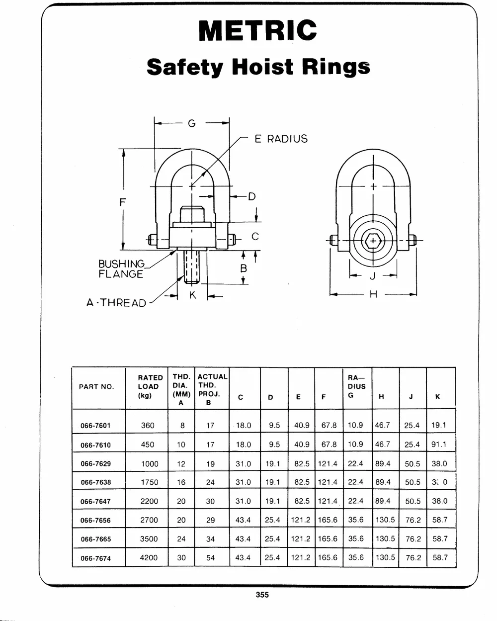
METRIC
Safety Hoist Rings
~_----_ G ---+ E RADIUS
po /
--| k--D
(TP) B
es
BFULSAHNIGNEG --_-- -- = omy
A-THREAD K
RATED| THD. |ACTUAL RA--
PART NO. LOAD | DIA. | THD. DIUS K
(kg) (MM)| PROJ. Cc D E F G H J
066-7601 A B
066-7610
066-7629 360 8 17 -18.0 95 | 409 | 67.8 |10.9 |46.7 | 25.4 | 19.1
066-7638
066-7647 450 10 17 18.0 95 | 409 | 67.8 |10.9 }46.7 | 25.4 | 91.1
066-7656 1000 12 19 31.0 | 19.1 82.5 }121.4 | 22.4 1894 | 50.5| 38.0
066-7665 1750 16 24 31.0 19.1 82.5 1121.4 | 22.4 189.4 | 505 | 3.0
066-7674
2200 20 30 31.0 19.1 82.5 |121.4| 22.4 |89.4 50.5 | 38.0
2700 20 29 43.4 | 25.4 1121.2 1165.6 | 356 [130.5] 76.2 | 58.7
3500 24 34 43.4 | 25.4 |121.2 }165.6 | 35.6 [130.5] 76.2 | 58.7
4200 30 54 43.4 125.4 |121.2 1165.6 | 35.6 |130.5| 76.2 | 58.7
735 AVOCA AVENUE, DORVAL, QUE., CANADA, H9P 1G4_ TEL. 514-631-9815 TELEX 05-822633
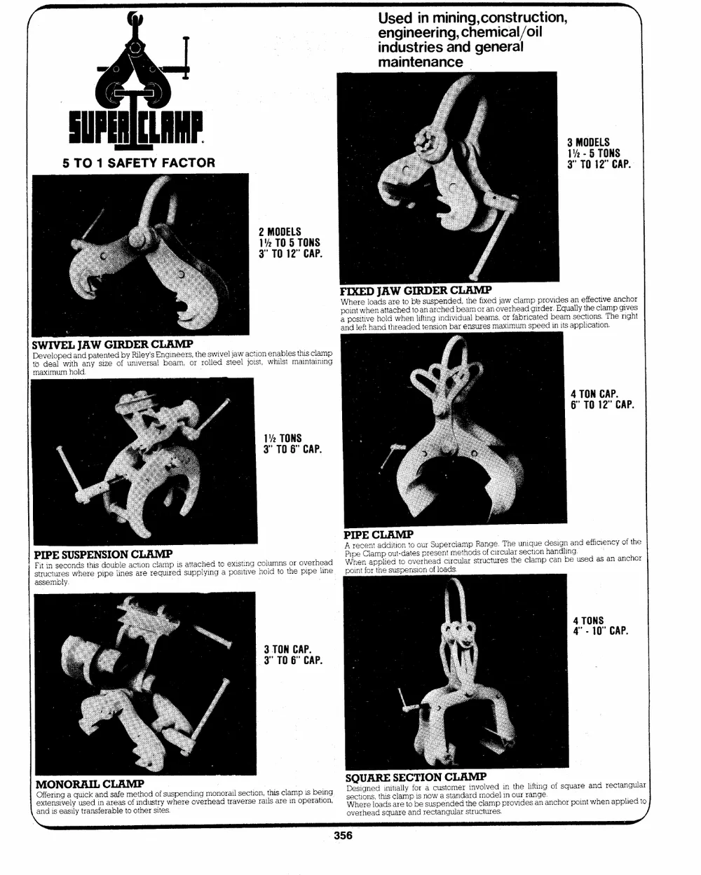
Used in mining,construction, \
engineering, chemical/oil
industries and general
maintenance |
a 3 MODELS
1% - 5 TONS
SUFERICLARF 3" TO 12" CAP.
5 TO 1 SAFETY FACTOR
2 MODELS
1% TO 5 TONS
3" TO 12" CAP.
FpWaaonhIpideonXstrlieweEtftihDvlheeoanaJhndaodstlAttdaarhWwcerhheteGaeoddnIbteoedlRiaftsntDeuinansgsErpicieoRnhnndedibCdevadibrLd,eueaatAnlhsmeubMorefreiaPasxmensmd,oajvxoaeriwrmfhcauelbamardmiscpgpaietrpdeeredodrv.biineEdqeaitusrsaaalspnlepycletitfichfoaeentcsict.olinvaT.emhpaengncighvhoetrs
SDtoeWvdeIelaVolpEewidLtahJndaAnpyaWtseinGzteeIdoRfbyDunREiivlReeyr'ssCalELngbieAnaemMe,rPs,orthreoslwleidvelstjeaewl ajcoitsito,n wehnialbsltesmatihnistacilnaimnpg
maximum hold.
4 TON CAP.
6" TO 12" CAP.
1% TONS
3" TO 6" CAP.
PsFitItruiPcntEusreeScsoUnwSdhsePrtEehiNspdiSopIuebOllieNneasCctaiLroenArceMlqauPmirpeids sautptpalcyhiendgtoa epxoissittiinvge choolludmtnos or opvieprehleiande : PAPWiIhrpePeecnECenlatCapmpaLldpideioAtuditMo-tondPaottoveseoruprhreeSasudepnectirmrccelutalhamropdsRstaronufgccteiu.rrceTushlaterheusnecicltqiauomenpdhecasnaidnlginbnega.nudseedffiacsieanncyanofchtoher
the
assembly. point for the suspension of loads.
4 TONS
4" - 10" CAP.
3 TON CAP.
3" TO 6" CAP.
MeOxftfOeernNisniOgveaRlyqAuuisIcekdLainnCdarsLaefaAes mMoef tPihndoudstorfyswuhspeernedionvgermhoenaodratirlavseecrtsieonr,ailtshiasrcelianmoppeisrabteiionn,g SsDWoeevhcQseteiriUroghneenAsae,lRddotahsEdiiqnssiutcaSairlarEelaelmytCaopnfTboidrseIrnsaeOoucwcstNuapasneCtgsnuotdlLmaeaendrrAdastthriMrenduvPccmotloluavdrmeeesdpl.piirnnootvuhirederlsainfatginen.ganocfhsoqrupaorient and rectangular
when applied to
and is easily transferable to other sites.